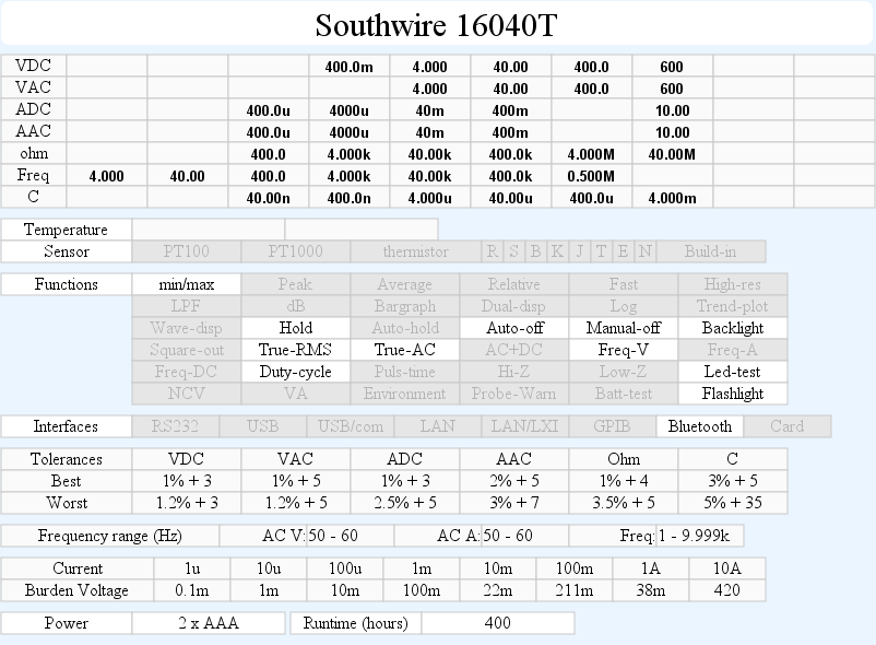
DMM Southwire 16040T
Image may be NSFW.
Clik here to view.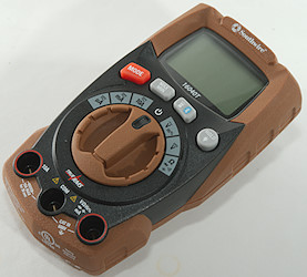
Southwire is an American wire and cable company and have a couple of DMM’s in their range. This is a fairly compact meter with most of the common DMM functions and a few extra.
Image may be NSFW.
Clik here to view.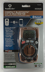 Image may be NSFW.
Clik here to view.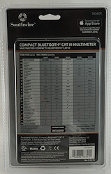
Image may be NSFW.
Clik here to view.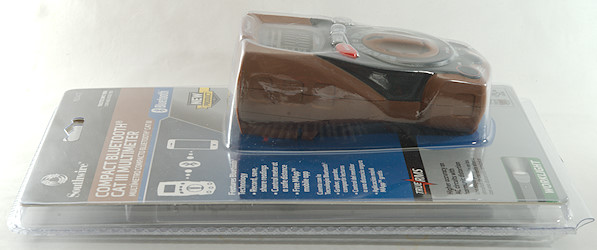
The meter is sold in a clamshell box with comparison to other Southwire meters on the back.
Image may be NSFW.
Clik here to view.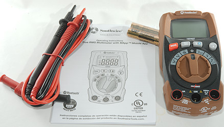
The box contains the meter, probes and a manual, it is also possible to download a manual.
Image may be NSFW.
Clik here to view.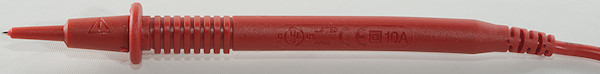
Image may be NSFW.
Clik here to view.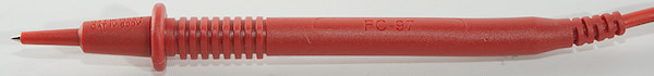
The probes are rated for 600V and 10A in CATIV environment, this is a very good rating.
Image may be NSFW.
Clik here to view.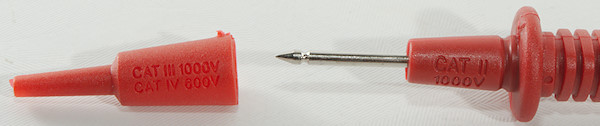
The removable tip must be on for best safety
Image may be NSFW.
Clik here to view.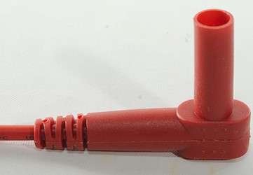
The standard size plug is fully shrouded.
Image may be NSFW.
Clik here to view.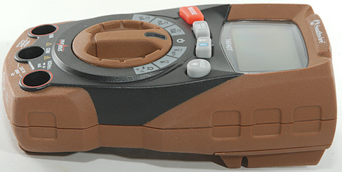
Image may be NSFW.
Clik here to view.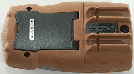
Image may be NSFW.
Clik here to view. Image may be NSFW.
Clik here to view.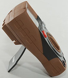
The tilting bale locks in both position (in and out). It might be possible to switch range on a non-slip surface, but it is difficult on a normal table.
Image may be NSFW.
Clik here to view.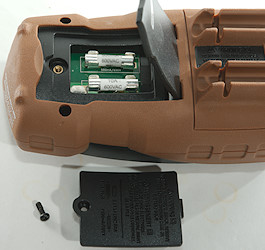 Image may be NSFW.
Clik here to view.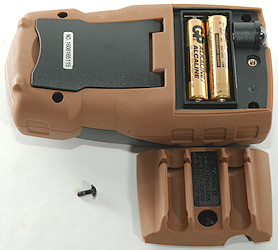
Both fuses and batteries can be replaces by removing a lid.
Image may be NSFW.
Clik here to view.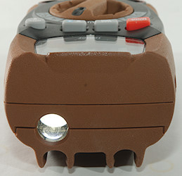
The flashlight.
Image may be NSFW.
Clik here to view.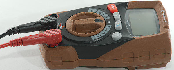
The probes looks fairly large on this small meter.
Image may be NSFW.
Clik here to view.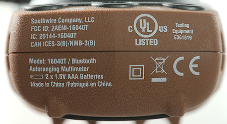
Display
Image may be NSFW.
Clik here to view.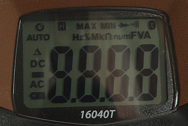
The above picture shows all the segments on the display, not all are used by the meter.
Image may be NSFW.
Clik here to view.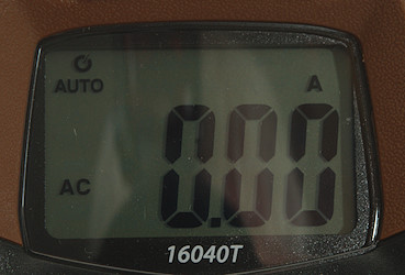
Typical display during usage, it will show the number and what measurement is selected.
The circle with arrow shows that auto power off is enabled, hold down MODE when turning on to disable this.
Functions
Image may be NSFW.
Clik here to view.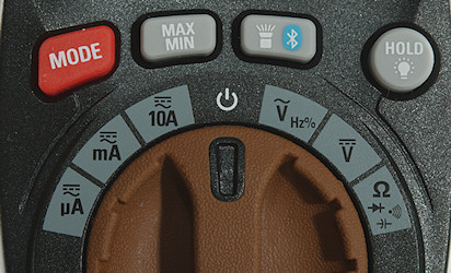
Buttons:
- Mode: Selects secondary ranges for each position on the range switch.
- Max/Min: Starts recording min/max. values, press the button to change between min/max, hold down to exit.
- Image may be NSFW.
Clik here to view.![flashlight]() : Turns on the flashlight, hold down to turn on Bluetooth.
: Turns on the flashlight, hold down to turn on Bluetooth. - Hold: Will freeze the display, hold down to use turn on backlight.

Rotary switch:
- uA: Current DC and AC, use MODE for DC.
- mA: Current DC and AC, use MODE for DC.
- A: Current DC and AC, use MODE for DC.
- Off: Meter is turned off
- VAC: Volt AC, frequency and duty cycle.
- VDC: Volt DC
- Image may be NSFW.
Clik here to view.![rangeOhm]() : Resistance, continuity, diode and capacitance
: Resistance, continuity, diode and capacitance

Input
Image may be NSFW.
Clik here to view.
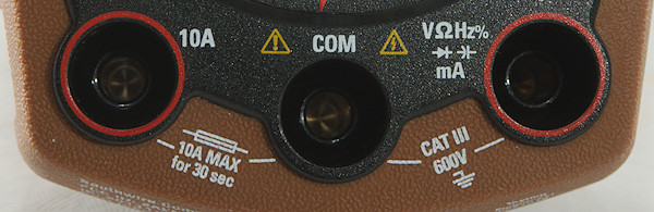
- 10A: High current, it can only withstand 10+ ampere for 30 seconds time (Fuse is 10A).
- COM: The common terminal for all ranges.
- xxx: All other ranges, included mA and uA. Having current range on the same terminal as voltage will increase the risk for mistakes.
Measurements
- Volt and frequency
- Frequency input requires a zero crossing.
- Max/min needs about 280ms to capture a voltage.
- At 0.1Vrms input frequency range is from 1Hz to 3kHz
- At 1Vrms input frequency range is from 1Hz to 43kHz
- At 7Vrms input frequency range is from 1Hz to 540kHz
- 1 VAC is 5% down at 2.1kHz, rms will not work at this frequency
- Input impedance is 6Mohm on DC and 10-11Mohm on AC, also in mV range.
- Ranges rated to 600V AC/DC
- Frequency input requires a zero crossing.
- Current
- Ranges rated with 10A/600V and 0.5A/600V fuse
- Ranges rated with 10A/600V and 0.5A/600V fuse
- Ohm, Continuity, diode and capacity
- Ohm is 0.97V open and 0.49mA shorted
- Continuity is very fast (About 10ms).
- Continuity beeps when resistance is below 50ohm
- Continuity is 1.0V open and 0.49mA shorted
- Diode range uses 3.2V, max. display is 3.000V at 0.19mA, max. current is 2.4mA shorted
- 3900uF takes about 7 seconds to measure.
- Ranges rated to 250V AC/DC
- Ohm is 0.97V open and 0.49mA shorted
- Miscellaneous
- Current consumption of meter is 11mA (18mA with backlight), Bluetooth adds 7mA.
- Flashlight uses 120mA with fresh batteries, at 2.4V the current is 160mA
- Meter works down to 1.8V where meter turns off, battery symbol show at 2.4V.
- Display loses contrast and viewing angle when battery drops in voltage also before the battery low symbol is shown.
- Backlight is independent of voltage.
- Reading is stable when battery voltage changes.
- The meter a few display update to reach the final value.
- Viewing angle is good
- Display updates around 2 times/sec
- Backlight will automatic turn off in 30 seconds.
- Flashlight do not have a timeout, but will turn off together with the meter (i.e. 15 minutes).
- Will automatic turn power off in about 15 minutes.
- Standard probes fits perfectly.
- Weight is 206g without accessories, but with batteries.
- Size is 121 × 66 × 47mm.
- Current consumption of meter is 11mA (18mA with backlight), Bluetooth adds 7mA.
- Probes
- Probe resistance 24mOhm for one
- Probe wire is soft and 80cm long.
- Probe resistance 24mOhm for one
Image may be NSFW.
Clik here to view.
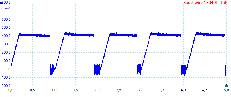
A look at the capacity measurement waveform, it is non-polarized.
Image may be NSFW.
Clik here to view.
Application
Image may be NSFW.
Clik here to view.
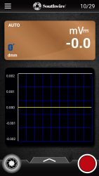 Image may be NSFW.
Clik here to view.
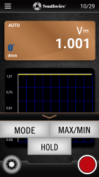 Image may be NSFW.
Clik here to view.
 Image may be NSFW.
Clik here to view.
The application will show the meter reading and can record the values. It is also possible to control the meter (Only the buttons, not the range switch).
The curve on the screen is moving fairly fast and will only show the last few seconds.
Tear down
Image may be NSFW.
Clik here to view.
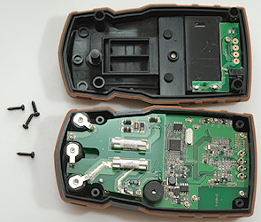
I had to remove 4 screws to open it.
Image may be NSFW.
Clik here to view.
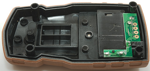
The back contains a circuit board with the flashlight led and connections from the batteries.
Image may be NSFW.
Clik here to view.
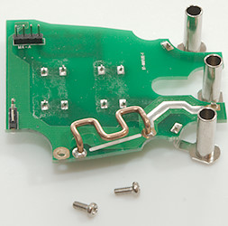
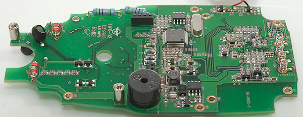
The circuit board is build to fit exactly into the DMM.
Image may be NSFW.
Clik here to view.
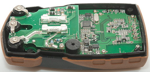
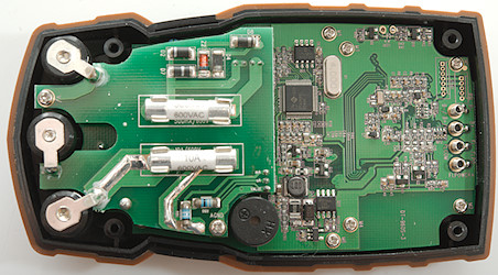
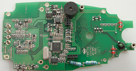
There is two layers of circuit board, the top layer with fuses and the input connections.
Image may be NSFW.
Clik here to view.
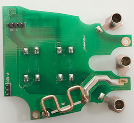 Image may be NSFW.
Clik here to view.
It was mounted with two screws and connectors for the signals.
Image may be NSFW.
Clik here to view.
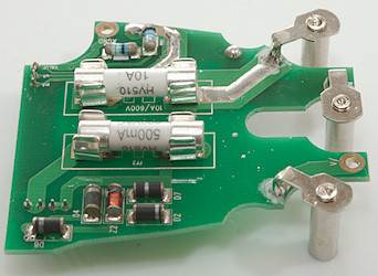 Image may be NSFW.
Clik here to view.

The two resistors (R80 & R81 99ohm & 1ohm) are the uA and mA shunts. At the connector is a mA, uA and a value connections, the value connections makes it possible to measure the voltage ignoring losses in the connector and switch.
The diodes (D2, D4, D7, D8 and Z2) are protection for the shunt resistors.
Image may be NSFW.
Clik here to view.
Image may be NSFW.
Clik here to view.
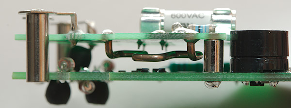
Image may be NSFW.
Clik here to view.
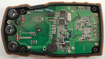
Image may be NSFW.
Clik here to view.
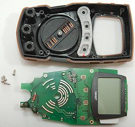
Four more screws and the circuit board could be removed.
Image may be NSFW.
Clik here to view.
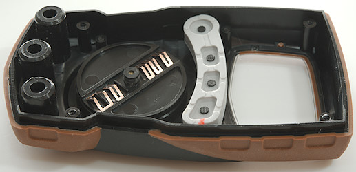
Image may be NSFW.
Clik here to view.

And four more screws to removed the lcd display.
Image may be NSFW.
Clik here to view.
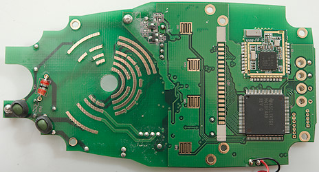
On this side is a microprocessor (U1: MSP430F449 16bit, 60+256K flash and 2K ram) and a Bluetooth module.
The input voltage is connected to this circuit board via a screw and there are a couple of PTC’s and a gas discharge arrestor
Image may be NSFW.
Clik here to view.
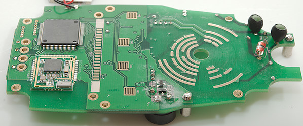
Image may be NSFW.
Clik here to view.
On this side there are a few more gas discharge arrestors and a PTC more. There is also some transistors used for protection (Q4 &Q6, Q3 & Q5). There is a resistor chain with smd (R103, R104, R105, R106, R107: 15Mohm) and one with through hole resistors (R31 & R32: 10Mohm).
The square chip is the multimeter chip (U9: DTA0660L) with its EEPROM (U10: 24LC02).
It looks like a boost circuit near the buzzer: U16 is the controller and Q22 and D3 the switching parts, this must be the reason for the stable backlight and flashlight.
Image may be NSFW.
Clik here to view.
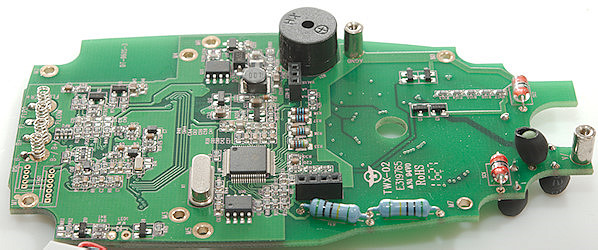
Image may be NSFW.
Clik here to view.
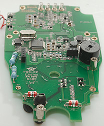 Image may be NSFW.
Clik here to view.
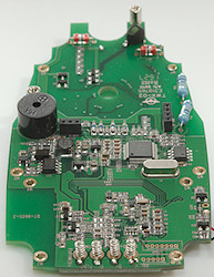
Image may be NSFW.
Clik here to view.
Conclusion
This is a rather small meter, but fairly thick. It has the most common functions for a DMM, it is only missing temperature. It adds Bluetooth and a flashlight. The shared voltage/current terminal is necessary for this small size, but is an added risk for mistakes.
The safety looks to be good, but I wonder about the fairly small fuse size.
I like the Bluetooth, it makes it easy to read the display from a few meters distance, but I am missing some alligator clips with the supplied probes.
It is not rated for high precision, but it is fairly precise, with exception of the low capacity range everything was only a few counts out.
This is a good meter both for mains related stuff and for hobby, it is easy to put into a pocket or toolbag, but I would keep it away from really high current stuff.
Notes
How do I review a DMM
More DMM reviews
My website with reviews of many chargers and batteries (More than 1000): http://lygte-info.dk/