DMM DT-830B
Image may be NSFW.
Clik here to view.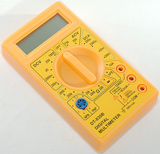
This is a really cheap DMM with manual ranges and a minimum of functions.
Image may be NSFW.
Clik here to view.
There was no box included with the DMM.
Image may be NSFW.
Clik here to view.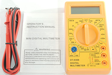
It included the DMM, a pair of probes and a instruction sheet.
The instruction sheet includes specifications for temperature measurement, battery test and also has text about fuse replacement, i.e. it do not match the meter, even though it has a fairly correct drawing of the meter..
Image may be NSFW.
Clik here to view.
The standard probes are rather tiny, but marked that they can handle 1000V.
Image may be NSFW.
Clik here to view.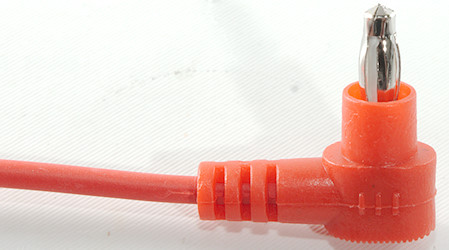
They use 4mm plugs, but they are not shrouded and very short.
Image may be NSFW.
Clik here to view.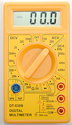 Image may be NSFW.
Clik here to view.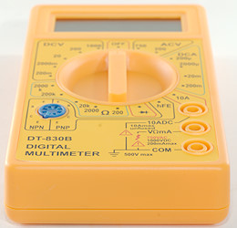
Image may be NSFW.
Clik here to view.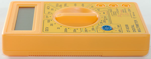
Image may be NSFW.
Clik here to view.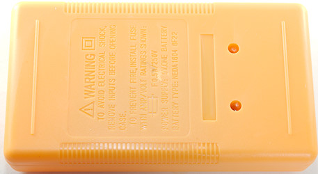
On the back it says to use a 0.5A fuse, but there is no fuse inside.
Image may be NSFW.
Clik here to view.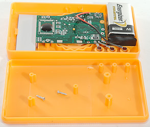
To replace the battery the meter must be opened
Display
Image may be NSFW.
Clik here to view.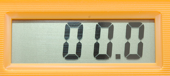
Typical display during usage, it will show the number.
Image may be NSFW.
Clik here to view.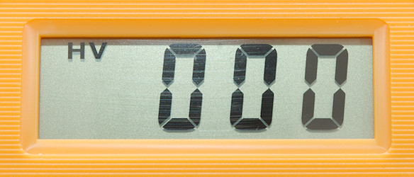
The HV letters is only shown in the 750/1000V ranges.
Functions
Image may be NSFW.
Clik here to view.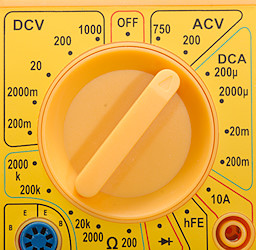
The range switch is not very precise and do not always connect correctly.
Rotary switch:
- Off: Meter is turned off
- VAC: 750 & 200: AC voltage ranges.
- ADC: 200u, 2000u, 20m, 200m, 10A: DC current range
- hFE: NPN & PNP: Transistor tester
- Image may be NSFW.
Clik here to view. : Diode test, but it do not show correct voltage.
 - Ohm: 200, 2K, 20k, 200k, 2M: Resistance range.
- VDC: 200m, 2, 20, 200, 1000: DC voltage range.
Input
Image may be NSFW.
Clik here to view.
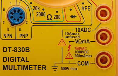
- 10ADC: 10A unfused DC current input.
- CON: The common terminal for all ranges.
- xxx: All other ranges, including mA. It is always problematic when a current range shares connector with a voltage range, if the switch is in the wrong position the meter will be damaged (at least).
- NPN/PNP: Transistor tester input.
Measurements
- Volt and frequency
- 7V AC readings is 5% down at 8kHz (Rectification error is not included).
- Input impedance is 1Mohm on DC
- Input impedance is 0.5Mohm on AC half the time.
- AC range uses a single diode, i.e. DC will show a (wrong) voltage if it has the correct polarity.
- The specifications says the input is protected to 1000VDC/750VAC, except mV that is protection to 250VAC
- 7V AC readings is 5% down at 8kHz (Rectification error is not included).
- Current
- 10A range will change significantly at 10A current due to heating.
- 10A range is unfused
- mA range is unfused (Manual says 0.5A fuse).
- 10A range will change significantly at 10A current due to heating.
- Ohm, continuity, diode and capacity
- Ohm needs about 1.5s to measure 100ohm in 200ohm range.
- Ohm voltage is 0.29V open in 2k and above ranges. Shorted is 80uA in 2k range down to 0.3uA in 2M range
- Ohm voltage is 3V open in 200ohm ranges and 1.8mA shorted
- Diode range uses 3V, max. display is 1.999V (Actual voltage is 1.3V) at 0.67mA, max. current is 1.2mA shorted
- Diode voltage reading mostly useless, but range can be used to test a diode.
- The specifications says the input is protected 250VAC for 15 seconds, I doubt it.
- Ohm needs about 1.5s to measure 100ohm in 200ohm range.
- Miscellaneous
- Current consumption of meter is 0.28mA except ohm with 0.5m and 200ohm/diode is 3.2mA
- Meter displays values down to 2.7V where it turns off, battery symbol shows at 6.2V.
- Readings will increase significantly in value below 4.2V (Shows about double voltage at 3.8V).
- Viewing angle is good
- Display updates around 2 times/sec
- Will not automatic turn power off
- Standard shrouded probes do not make contact, but banana plugs can be used.
- The meter need some display update to reach the final value.
- Weight is 106g without accessories, but with batteries.
- Size is 123 × 68 × 25mm
- Current consumption of meter is 0.28mA except ohm with 0.5m and 200ohm/diode is 3.2mA
- Probes
- Probe resistance 98mOhm for one.
- Probe wire is fairly soft and thin, they are 57cm long.
- Probe resistance 98mOhm for one.
Image may be NSFW.
Clik here to view.

I do not believe the specified tolerances, the included manual did not match the DMM.
On 2000uA range the meter is unstable (probably the switch) and may show 30% too much sometimes.
On 10A range the shunt will heat up and the meter go show more 11A with 10A current.
The low ohm range shows too low a value (100ohms can shows 90ohm).
Tear down
Image may be NSFW.
Clik here to view.
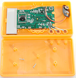
Two screws and the back could be removed, this is required to replace the battery.
Image may be NSFW.
Clik here to view.
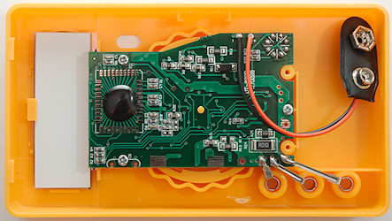
The circuit board is minimal in size.
Image may be NSFW.
Clik here to view.
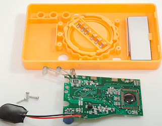
Three screws more and I could remove the circuit board.
Image may be NSFW.
Clik here to view.
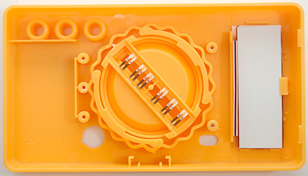
I left the LCD display and zebra stripe in.
Image may be NSFW.
Clik here to view.
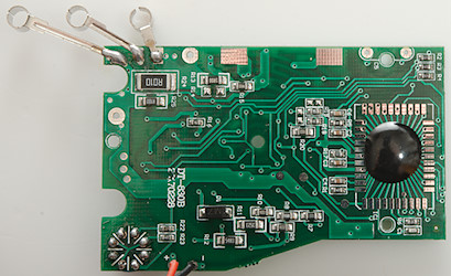
There is not many parts on the circuit board. At the input terminals is some of the resistors for the current ranges: 10A (R24: 0.010ohm R25: 0.100ohm), 200mA (R13: 1.00ohm), 20mA (R15: 9.00ohm + R13), 2000uA (R7: 100ohm), 200uA (R8: 900ohm + R7).
The resistors (R12, R10, R10, R8, R19, R7) is also used for voltage input and the diode (D1) is used for rectification in the AC voltage ranges.
There is no trimpot this probably means that the IC contains a EEPROM and some calibration values are stored in it during final test.
Image may be NSFW.
Clik here to view.
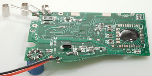
Image may be NSFW.
Clik here to view.
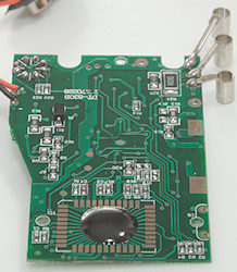 Image may be NSFW.
Clik here to view.
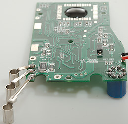
Image may be NSFW.
Clik here to view.
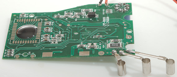
Image may be NSFW.
Clik here to view.
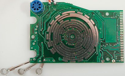
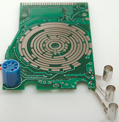
On this side of the circuit board is the range switch and the transistor tester socket. It also looks like some “dirt” on the circuit board
Image may be NSFW.
Clik here to view.
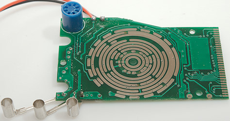
Image may be NSFW.
Clik here to view.
Conclusion
This is a well known and very cheap meter, usual it is fairly precise, but occasionally there is intermittent contact in the range switch and it shows a wrong value.
It is very limited in ranges and functions and with a wrongly working diode range.
There is nothing that looks like input protection or fuses, i.e. keep it away from mains and high current.
I do not like this meter it is not reliable enough.
Notes
This meter exist in more than one version with the same type number.
How do I review a DMM
More DMM reviews
My website with reviews of many chargers and batteries (More than 1000): http://lygte-info.dk/
