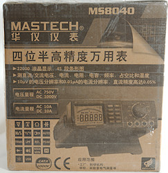
DMM EEVBlog 121GW
Image may be NSFW.
Clik here to view.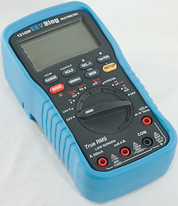
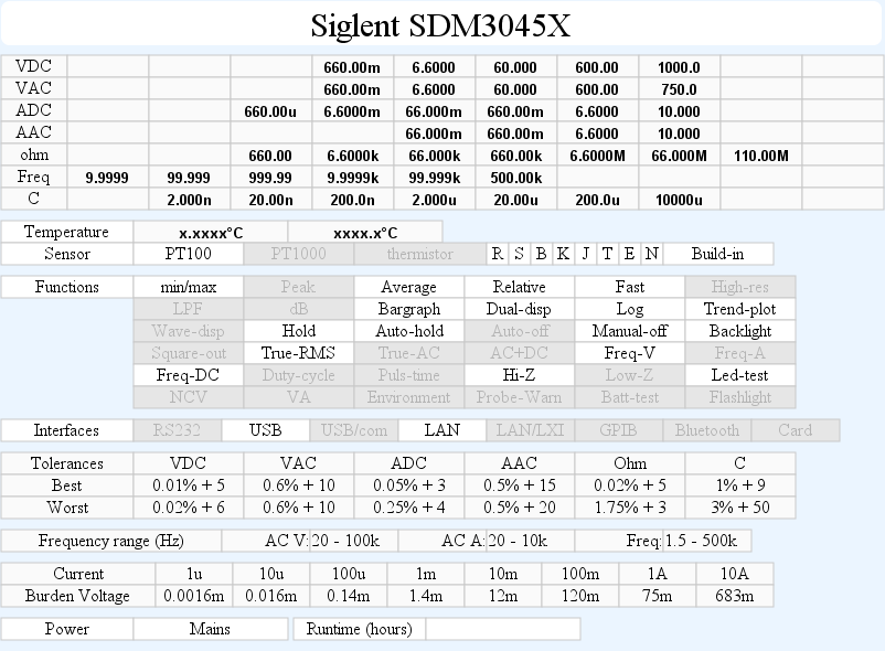
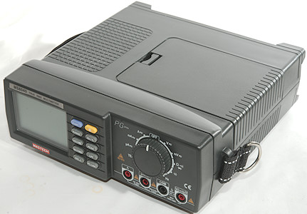
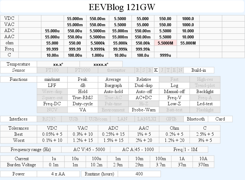
This meter is partly specified by Dave from EEVBlog and made by UEI, it is packed with function, including some unique ones.
Image may be NSFW.
Clik here to view.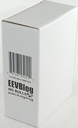
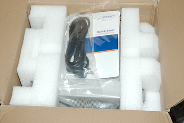
The meter arrived in a white cardboard box with very little text on it.
Image may be NSFW.
Clik here to view. Image may be NSFW.
Clik here to view.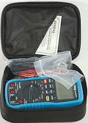
Inside was the pouch with the meter in it.
Image may be NSFW.
Clik here to view.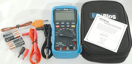
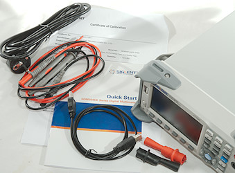
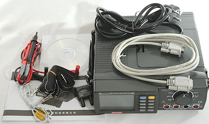
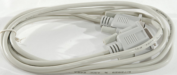
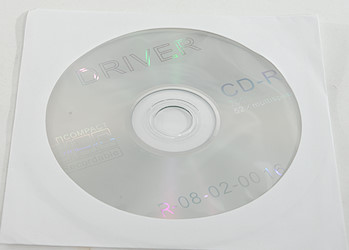
The box included the meter, two probes, a thermocoupler, batteries, pouch and a Certificate of Conformity. There is no manual, it must be downloaded from the EEVBlog website.
Image may be NSFW.
Clik here to view.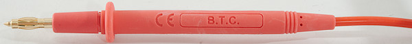
Image may be NSFW.
Clik here to view.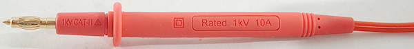
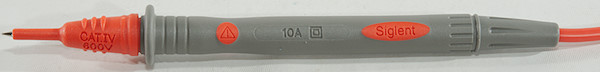
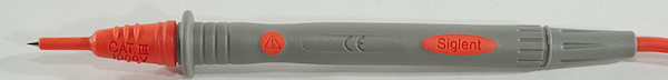
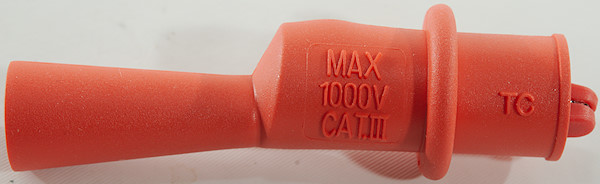
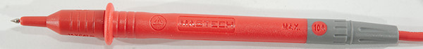
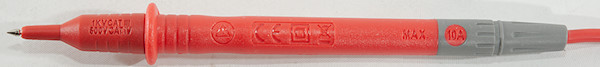
Probes are branded with B.T.C. and are rated for up to CAT IV 1000V. The meter is “only” CAT III 600V.
Image may be NSFW.
Clik here to view.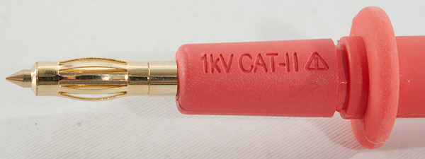
Image may be NSFW.
Clik here to view.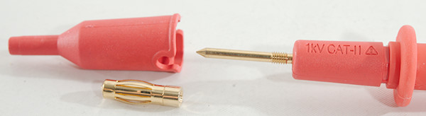
Image may be NSFW.
Clik here to view.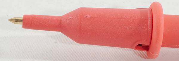
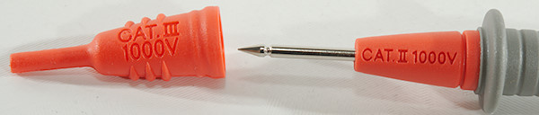
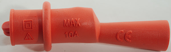
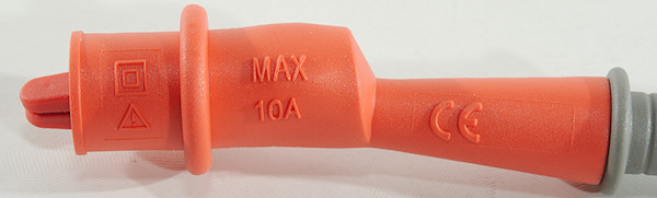
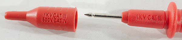
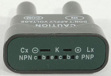
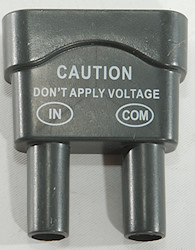
The tip has 3 different configurations.
Image may be NSFW.
Clik here to view.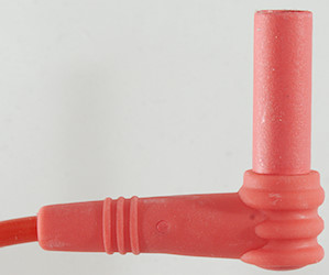
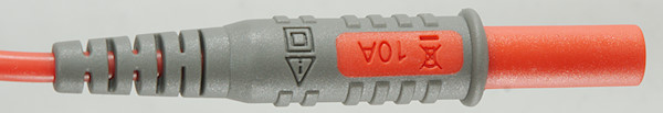
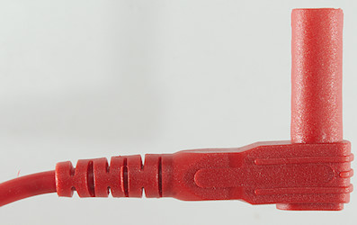
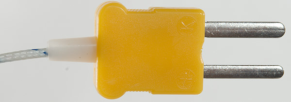
The plug is fully shrouded and standard probe plug size.
Image may be NSFW.
Clik here to view.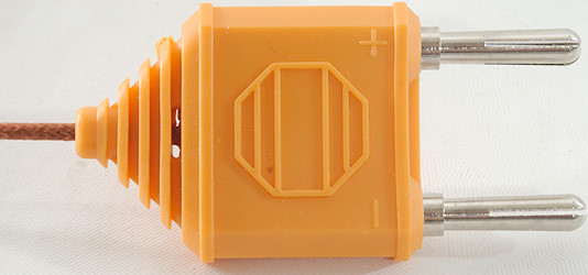
Image may be NSFW.
Clik here to view.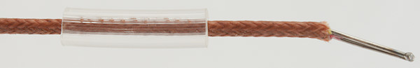
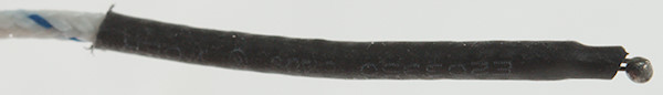
A standard thermocoupler with a standard dual banana connector.
Image may be NSFW.
Clik here to view.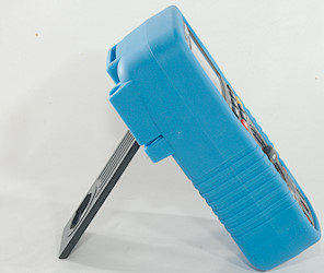 Image may be NSFW.
Clik here to view.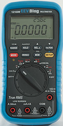
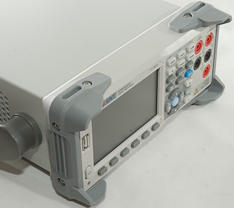
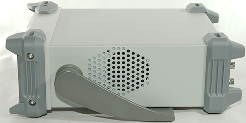
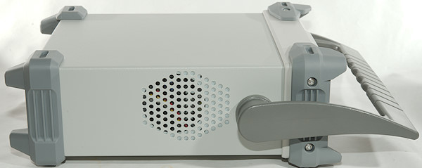
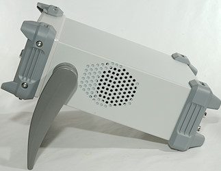
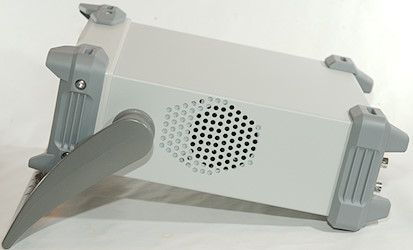
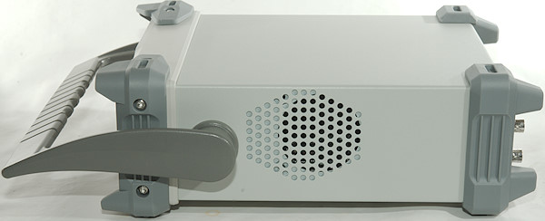
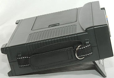
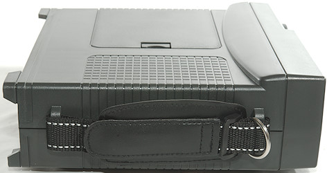
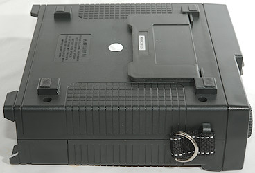
The meter is heavy and the tilting bale can hold it while the range switch is used and when the buttons is pressed carefully.
Image may be NSFW.
Clik here to view.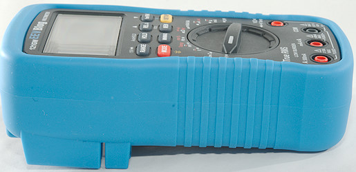
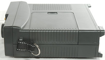
The meter is rather thick.
Image may be NSFW.
Clik here to view.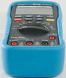 Image may be NSFW.
Clik here to view.
Image may be NSFW.
Clik here to view.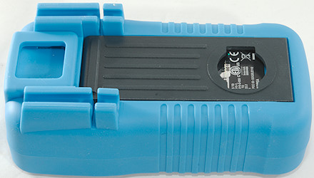
Image may be NSFW.
Clik here to view.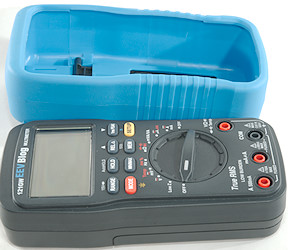
Image may be NSFW.
Clik here to view.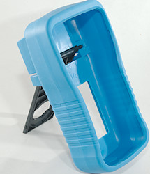
Image may be NSFW.
Clik here to view.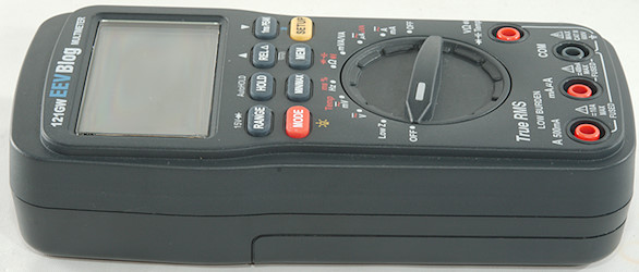
Image may be NSFW.
Clik here to view.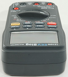 Image may be NSFW.
Clik here to view.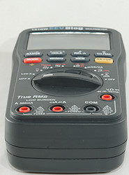
Image may be NSFW.
Clik here to view.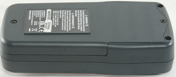
Image may be NSFW.
Clik here to view.
Image may be NSFW.
Clik here to view.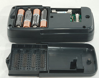
Image may be NSFW.
Clik here to view.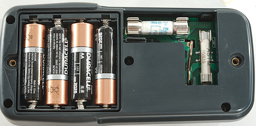
Image may be NSFW.
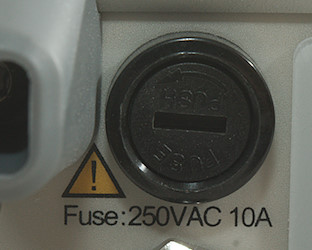
Clik here to view.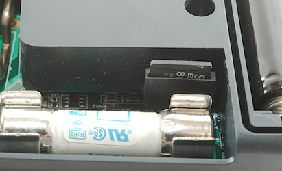
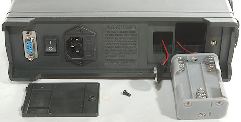
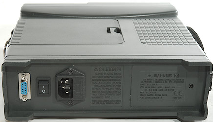
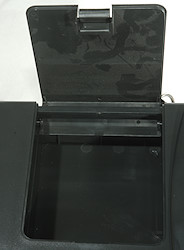
There is a micro SD card next to the fuse, it is used for firmware updating, for logging and the calibration can be stored on it.
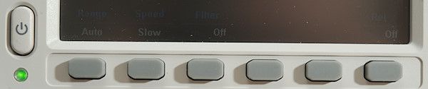
Display
Image may be NSFW.
Clik here to view.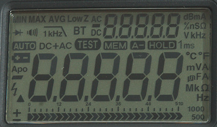
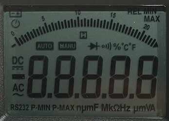
The above picture shows all the segments on the display.
Image may be NSFW.
Clik here to view.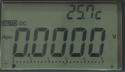
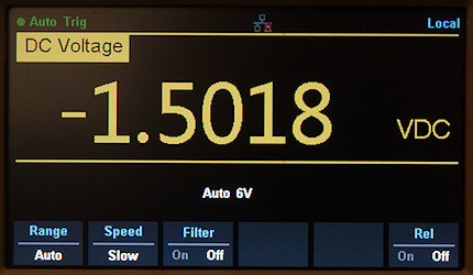
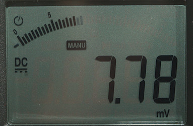
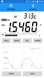
Normal DC voltage with voltage, bargraph and temperature. The secondary display will often shows meter temperature.
Image may be NSFW.
Clik here to view.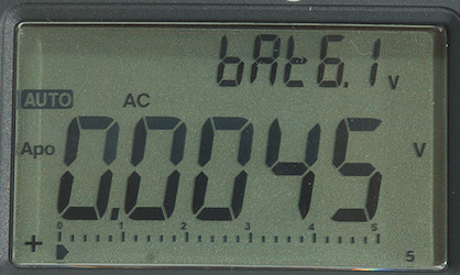
Battery voltage, it requires one or more presses on SETUP to display it.
Image may be NSFW.
Clik here to view.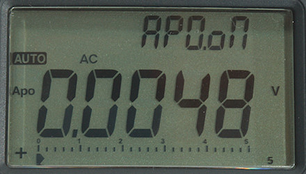
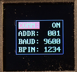
A configuration options (Auto Power Off), to change it: Hold SETUP down until it blinks, then use arrows to change it, hold SETUP to save value.
Image may be NSFW.
Clik here to view.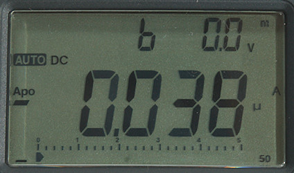
Burden voltage, it is in mV, but the m is placed a bit far from the V.
The secondary display has a couple of functions:
- Meter internal temperature (Ambient temperature)
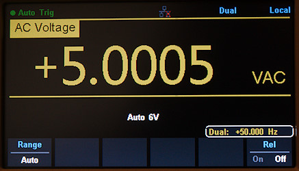
- Frequency in VAC and mVAC mode.
- dBm in VAC mode.
- Optional burden voltage in current modes
- Volt and current in VA modes (Toggles between them).
- Diode test voltage, either 3V or 15V
- Entries when logging to card or displaying data
- Configuration settings.
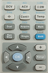
Functions
Image may be NSFW.
Clik here to view.
Buttons (Range selection and a few other are remembered):
- Range: Switch to manual range and select range, hold down to activate automatic ranging again. In diode mode it will switch to 15V diode test
- Hold: Freeze the display, press again to for automatic hold when reading is table and press a 3. time for to return to normal mode.
- REL: Store current reading and show further readings relative to this value. Hold down to active LPF in VAC.
- 1msPeak: Capture peak voltage, this only work in VAC where it will capture a positive or negative peak, result is without any sign. Hold down to turn bluetooth on.
- Mode: Select the red function on the rotary switch (These selection are remembered). Hold down to turn background light on.
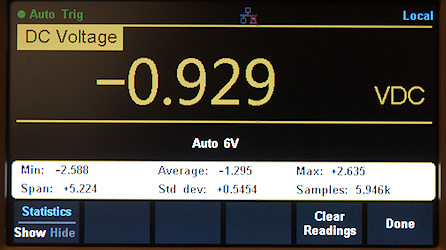
- Min/Max: Capture min/max/avg values, there is a position to show actual value. Hold down to disable.
- Mem: Press to see saved values, hold down to start logging. Time interval is changed in configuration.
- Setup: Controls secondary display and configuration, hold down to change and hold down to confirm changes.
The two arrows above REL and 1msPEAK are used together with MEM and SETUP.
REL, MIN/MAX, 1msPEAK and MEM disables autorange.
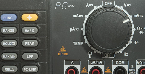
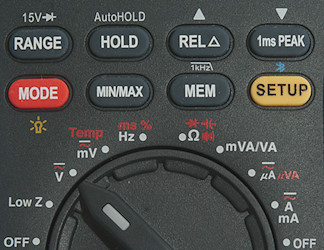
Rotary switch:
- Off: Meter is turned off.
- LowZ: Low impedance voltage measurement, meter is fixed in 600V range and can measure both AC and DC.
- V: Voltage DC, AC, AC+DC, in AC it is possible to show dBm on secondary display (Use SETUP)
- mV, Temp: Millitvolt DC, AC and temperature from thermocoupler
- Hz: Frequency, 1/frequency (ms) and duty cycle.
- Image may be NSFW.
Clik here to view.![ohm]() : Resistance, continuity, diode and capacity. Use the RANGE switch for 15V diode test.
: Resistance, continuity, diode and capacity. Use the RANGE switch for 15V diode test. - mVA/VA: Volt Ampere for DC and AC, this function requires connections to both volt and current terminals on the meter.
- uA/uVA: Micro ampere and micro volt ampere for both DC and AC
- A/mA: Milli ampere and ampere for AC and DC.
- Off: Meter is turned off.

dBm uses 600ohm reference impedance.
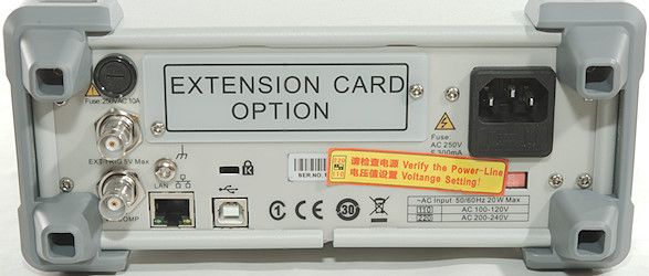
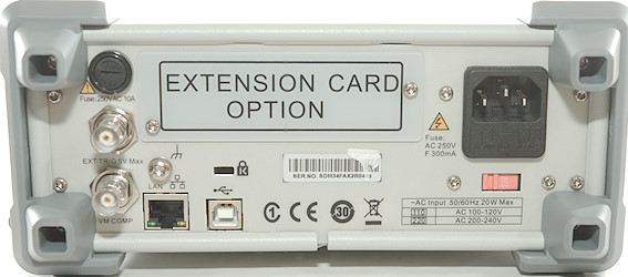
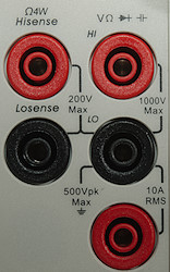
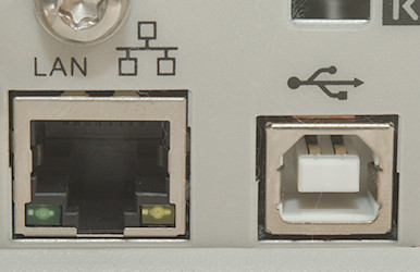
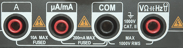
Input
Image may be NSFW.
Clik here to view.
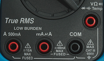
- A 500mA: The high mA range and the A ranges, also used for VA.
- mAuA: The lower current ranges, also used for VA.
- CON: The common terminal for all ranges.
- xxx: All other ranges including VA and burden voltage.
Measurements
- Volt and frequency
- Frequency input will trigger on 1V rms as long as the average voltage is within +/- 2.3V
- At 1Vrms frequency input range is from 1Hz to 1MHz
- Duty cycle works from 10% to 93% at 100kHz with 4Vpp, precision is within 1.6
- Duty cycle works from 1% to 99% at 10kHz with 4Vpp, precision is within 0.3
- The ms reading do not show pulse width, it is 1/frequency.
- 1 VAC is 5% up at 134kHz (RMS will not work at the frequency).
- 1 VAC with LPF (1kHz) is 5% down at 520Hz.
- Pressing the SETUP key will show dBm on the secondary display in AC.
- Max/min needs about 490ms to capture a voltage.
- Peak needs about 0.9ms to capture a voltage, it only captures a peak without sign and only in AC mode.
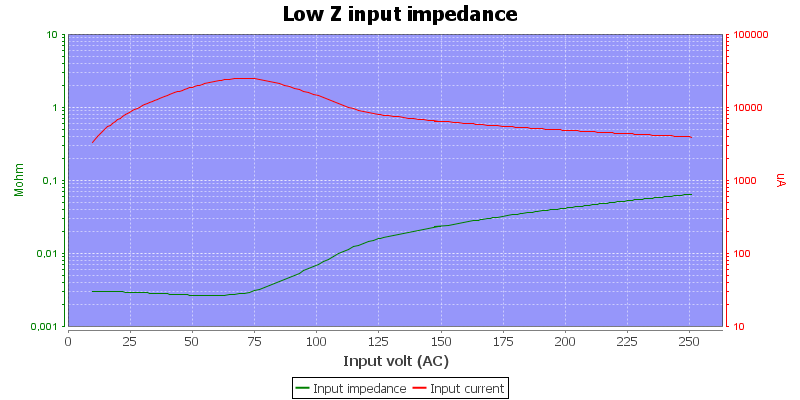
- Input impedance is 10-11Mohm on DC and 10Mohm on AC, AC+DC will switch between the two.
- mV DC/AC has 10Mohm input impedance up to about 2V, then it drops to a two kOhm
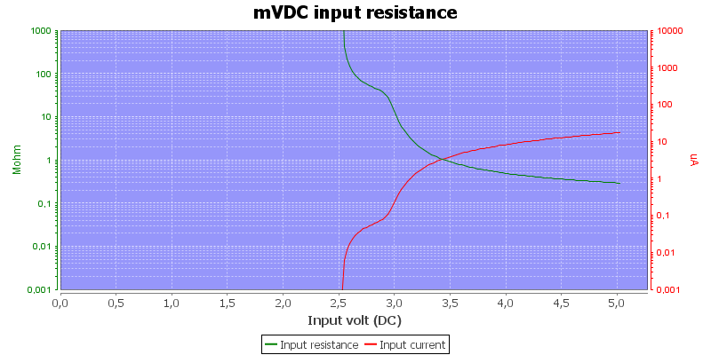
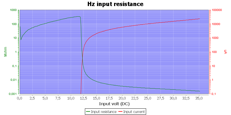
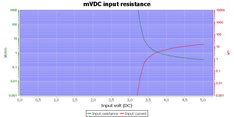
- Frequency input is a few Mohm up to 2 volt then it drops to 2kohm
- LowZ can show both AC and DC voltage, but requires at least 12V.
- Rated overload protection is 600VDC/VAC.
- Frequency input will trigger on 1V rms as long as the average voltage is within +/- 2.3V
- Current
- For best precision REL must be used in the low ranges (55uA, 5.5mA, 550mA), due to internal offset in the meter, this disables auto range.
- 10A range will show “OFL” above 11A
- Ampere ranges are not the usual distribution, the A terminal has 3 ranges (0.5A, 5A, 10A), this means the meter has one more current range than is typical.
- The meter can display burden voltage on secondary display (Hold SETUP, press arrow, hold SETUP, press SETUP), the value is in mV.
- The meter can measure VA (Volt x ampere), the secondary display will toggle between current (mA/A) and voltage, the primary display will show VA
- The VA ranges only works up to 55V.
- Overload protection in uA and mA: 0.4A/600V or 0.44A/600V 6×32mm fuse
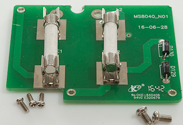
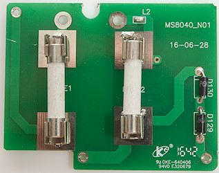
- Overload protection in A: 11A/1000V 10×38mm fuse
- There is an audible warning when using non current ranges with a probe in current terminals
- For best precision REL must be used in the low ranges (55uA, 5.5mA, 550mA), due to internal offset in the meter, this disables auto range.
- Ohm, continuity, diode and capacity
- Ohm needs about 4.5s to measure 100ohm
- Ohm is 2.5V open and 0.57mA shorted
- The Mohm ranges are very sensitive and will jump a bit around.
- Continuity is quick (about 25ms).
- Continuity beeps when resistance is below 30ohm (30ohm setting) and 300ohm (300ohm setting)
- Continuity has selection between 30ohm, 300ohm shorted or open in SETUP menu.
- Continuity is 2.1V open and 0.57mA shorted
- Diode range 3V uses 3.2V, max. display is 3.0000V at 0.05mA, max. current is 0.84mA shorted
- Diode range 15V uses 15.5V, max. display is 15.000V at 0.23mA, max. current is 4.7mA shorted
- 10uF takes about 4 seconds to measure.
- 9000uF takes about 16 seconds to measure.
- Rated overload protection is 600VDC/VAC
- Ohm needs about 4.5s to measure 100ohm
- Miscellaneous
- Current consumption of meter is 5mA-6mA (17mA with backlight)
- Bluetooth adds about 5mA to current consumption.
- Build-in battery voltmeter is about 0.2V too low on my meter.
- Meter works down to 1.7V where it turns off, battery symbol is show at 4.3V (4.0V on internal meter).
- The meter reading is stable down to 3.8V where it starts to show wrong values.
- Backlight start to fade at 3.5V
- The meter often needs a couple of updates before the reading is fully correct.
- Viewing angle is good
- Display updates around 5 times/sec
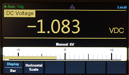
- Bargraph updates much faster than number (Probably 30+ times/second).
- Backlight will not turn automatic off
- Will automatic turn power off in about 30 minutes without any warning.
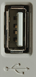
- Standard probes fits perfectly into sockets on meter.
- Firmware can be updated from a microSD card
- Weight is 486g without accessories, but with sleeve and batteries.
- Size is 165 × 84 × 55mm with sleeve.
- Current consumption of meter is 5mA-6mA (17mA with backlight)
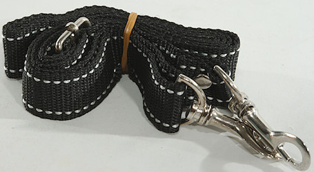
- Probes
- Probe resistance 29mOhm for one.
- Probe wire is soft and 100cm long.
- Probe resistance 29mOhm for one.
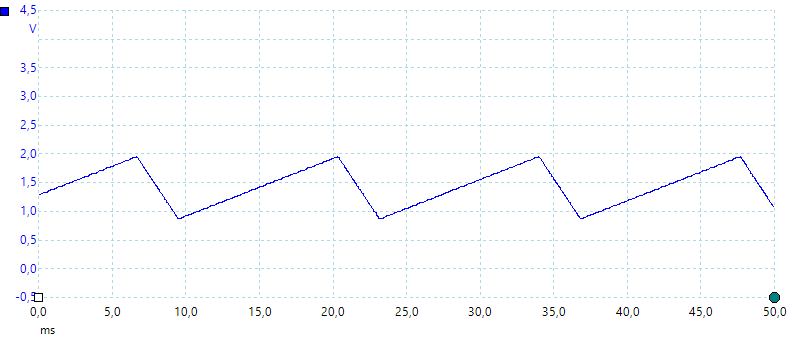
Image may be NSFW.
Clik here to view.
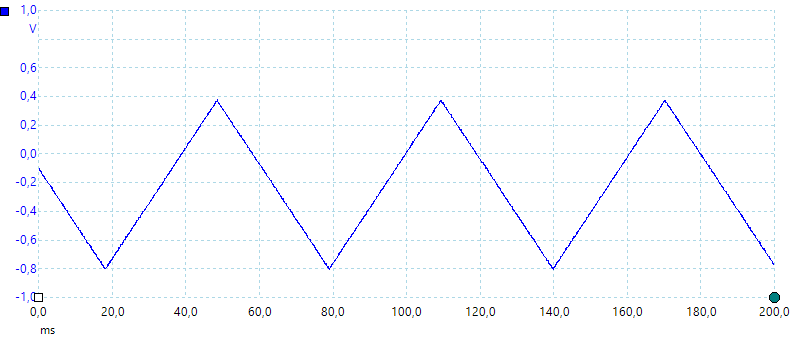
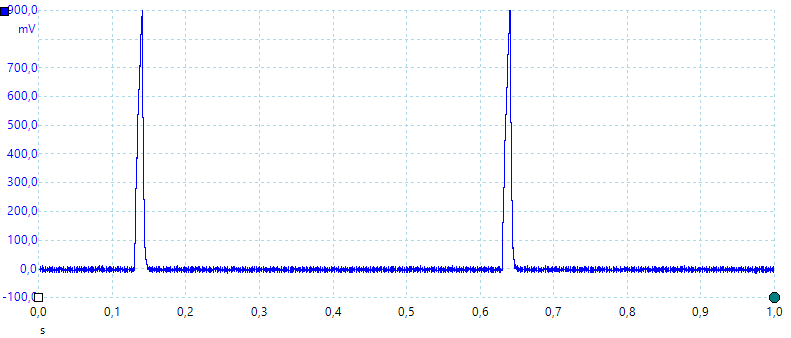
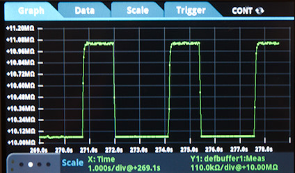
A look at the capacity measurement waveform.
Image may be NSFW.
Clik here to view.
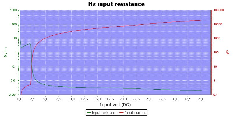
Frequency input resistance.
Image may be NSFW.
Clik here to view.
The LowZ uses a MOV with about 1W power dissipation.
Image may be NSFW.
Clik here to view.
Input impedance in DC+AC 5V range, the 11Mohm is DC, the 10Mohm is AC.
Image may be NSFW.
Clik here to view.
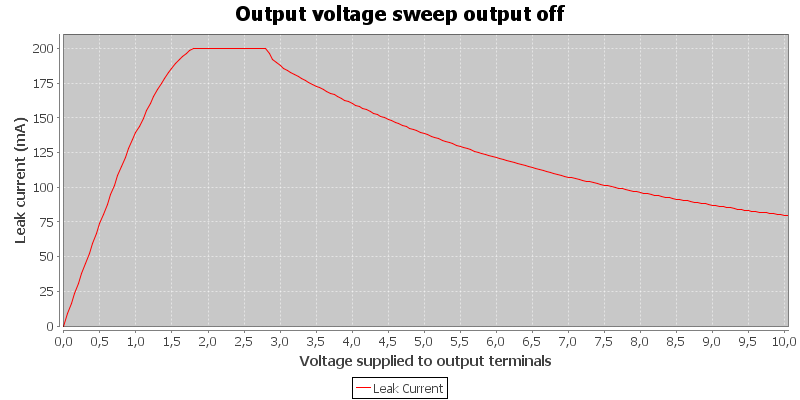
High DC voltage can block for AC readings.
The 5Mohm range is unstable at 1Mohm and jumps a bit more than 1%, this is more than the specified 0.3%.
I had some trouble with autoranging in AC+DC and when showing burden voltage.
Runtime is without Bluetooth.
Logging on card
Image may be NSFW.
Clik here to view.
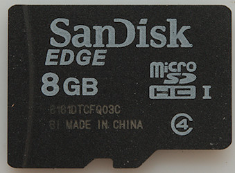
The meter is supplied with a micro SD card mounted in the internal reader. To get it out the sleeve and two screws must be removed.
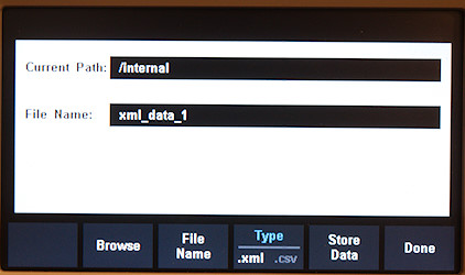
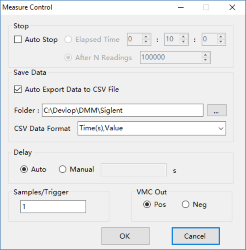
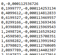
The logfile is in CSV format, but cannot be configured to support European CSV format.
Image may be NSFW.
Clik here to view.
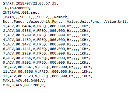
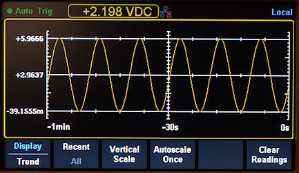
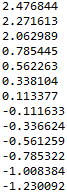
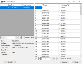
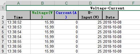
The top define the starting time and logging interval, the actual logging is the main display and sometimes auxiliary values. These auxiliary values are fixed and do not depend on what is shown in the secondary display.
Image may be NSFW.
Clik here to view.
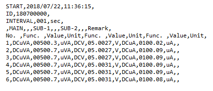
With VA the logging contains 3 values.
Image may be NSFW.
Clik here to view.
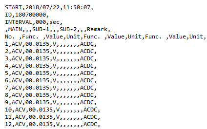
AC+DC is marked as ACV with ACDC option. Here I selected fast logging (Interval 0), this logs 5 times each second.
Software
Image may be NSFW.
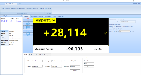
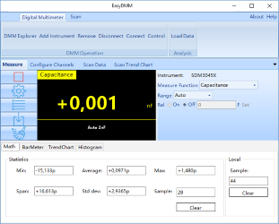
Clik here to view.
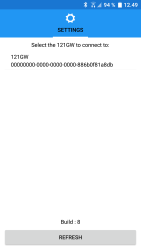
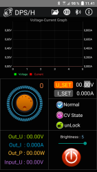
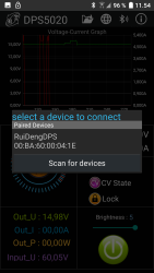
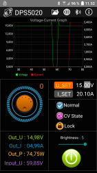
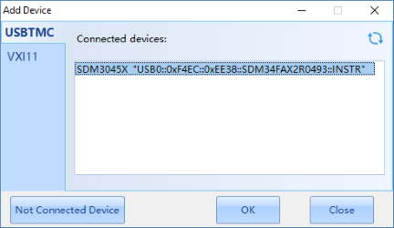
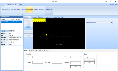
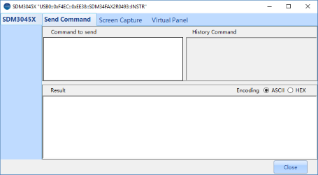
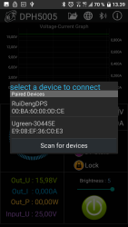
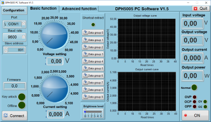
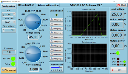
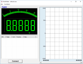
The software will scan for 121GW meters and one (or more) can be selected.
Image may be NSFW.
Clik here to view.
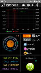
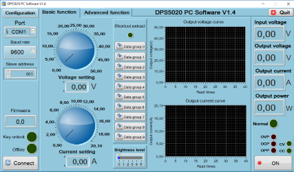
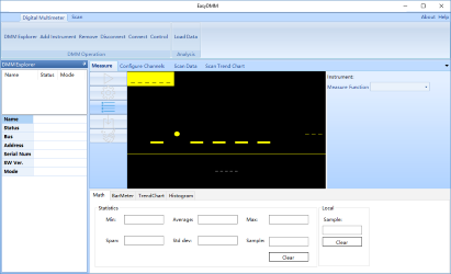
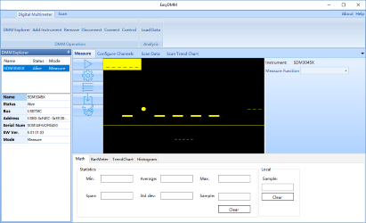
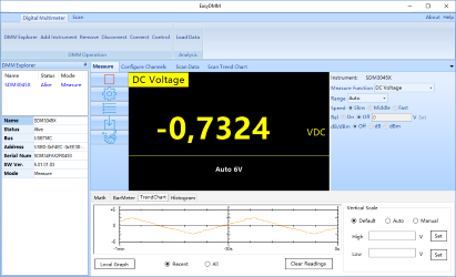
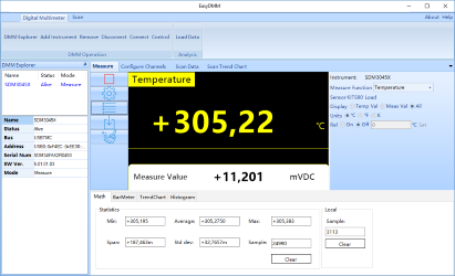
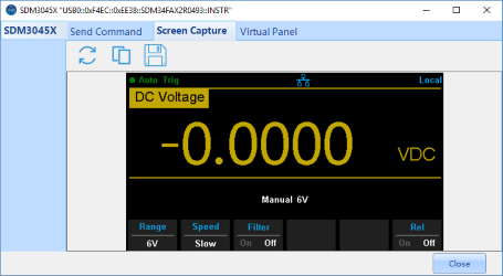
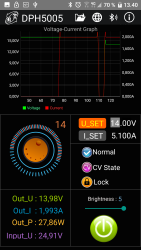
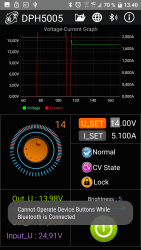
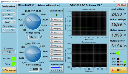
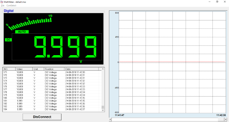
This is the standard readout in the software, it reflects the display on the meter. Some of the buttons on the meter is also accessible.
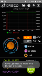
A bad connection will lock the display, the software do not reconnect automatic when in range again, instead SETTINGS and RESCAN must be used and a extra meter will show up.
Image may be NSFW.
Clik here to view.
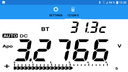
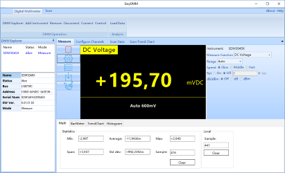
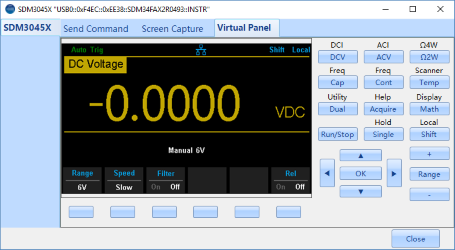
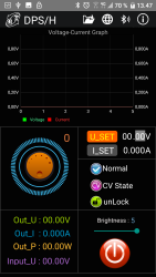
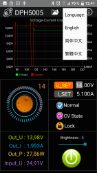
Turning the phone horizontal will increase the display size.
Image may be NSFW.
Clik here to view.
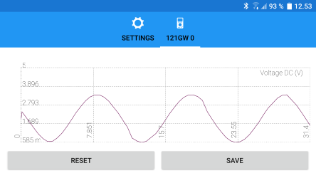
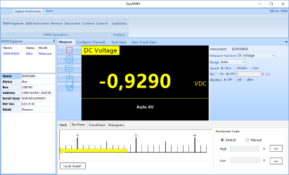
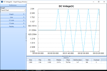
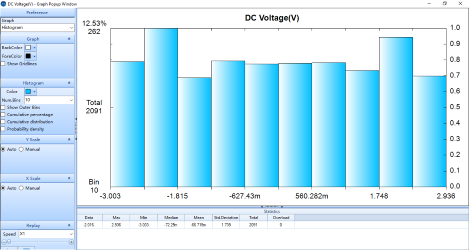
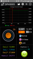
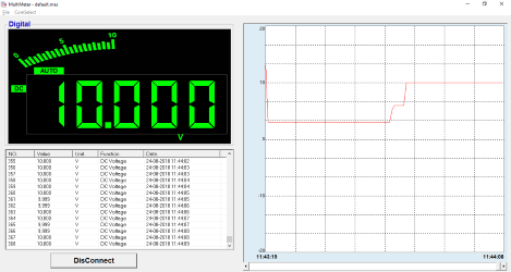
And a tap on the display will change to the chart or back. It is possible to zoom in and out on the chart.
The SAVE button will make a logfile that can be saved to a lot of different Android software, I used email.
Image may be NSFW.
Clik here to view.
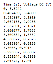
The email log contains a time stamp and the value from the chart, no secondary values will be included.
Tear down
Image may be NSFW.
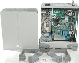
Clik here to view.
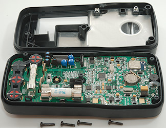
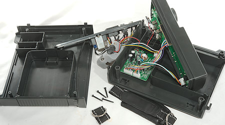
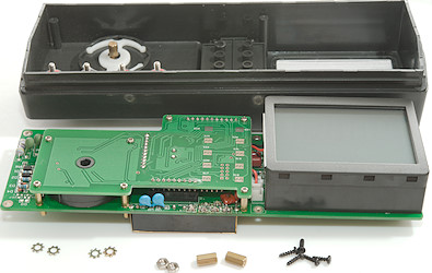
I addition to the battery cover I had to remove four screws to get inside the meter.
Image may be NSFW.
Clik here to view.
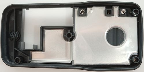
Image may be NSFW.
Clik here to view.
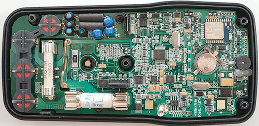
Image may be NSFW.
Clik here to view.
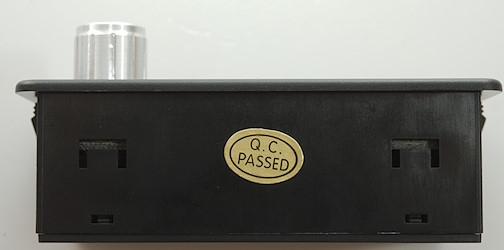
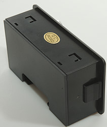
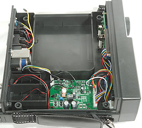
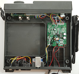
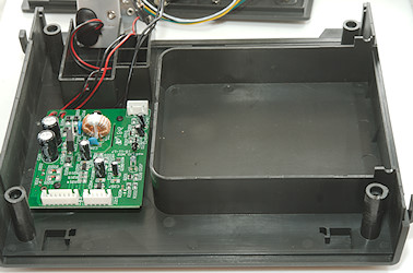
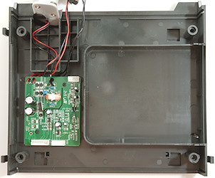
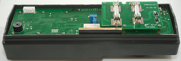
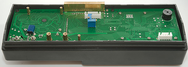
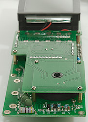
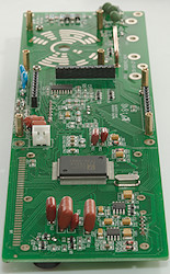
As usual the circuit board is shaped to fit the enclosure.
Image may be NSFW.
Clik here to view.
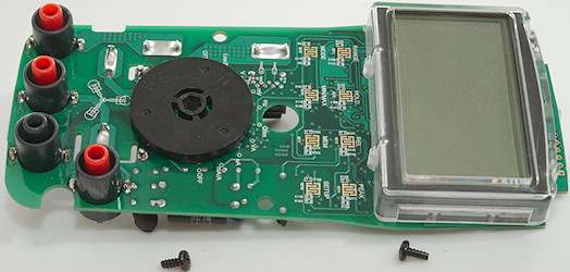
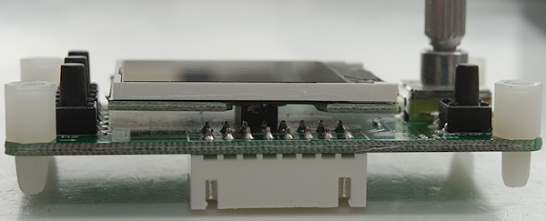
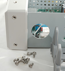
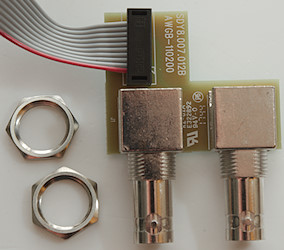
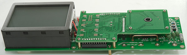
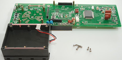
Two more screws and I could get the circuit board out.
Image may be NSFW.
Clik here to view.
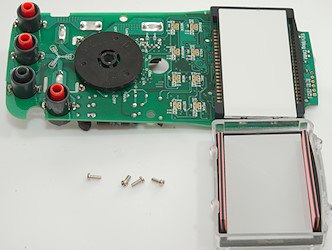
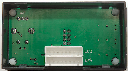
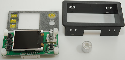
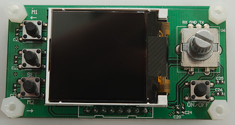
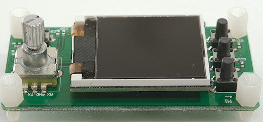
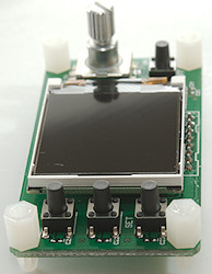
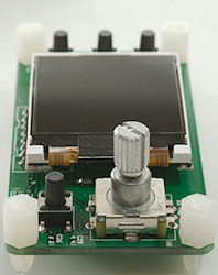
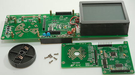
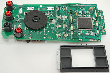
Four more screws to remove the LCD display.
Image may be NSFW.
Clik here to view.
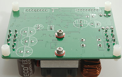
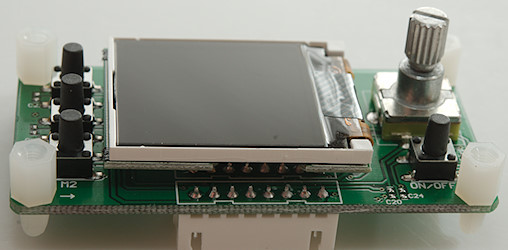
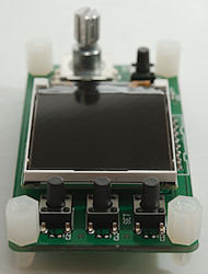
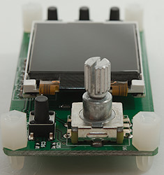
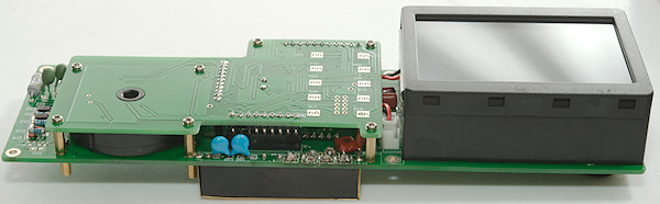
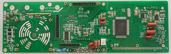
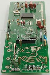
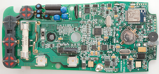
The backlight panel is soldered to the circuit board, I had to unsolder it to see the microprocessor.
Image may be NSFW.
Clik here to view.
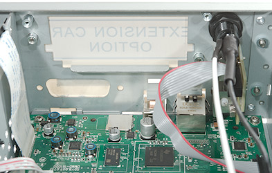
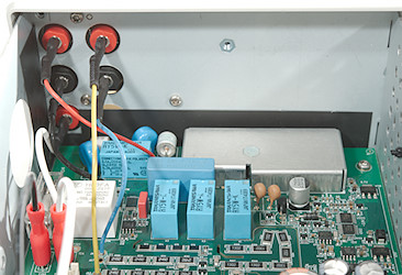
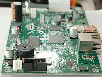
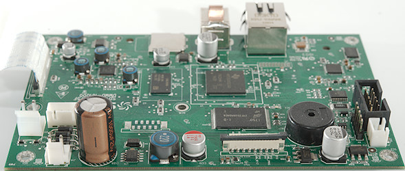
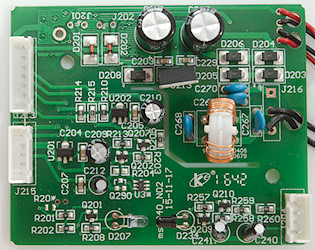
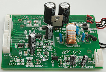
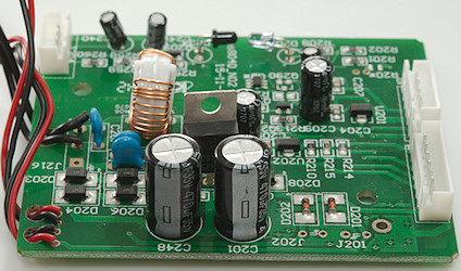
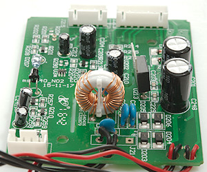
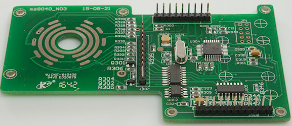
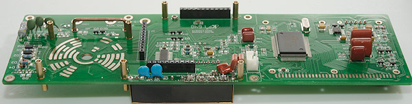
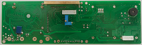
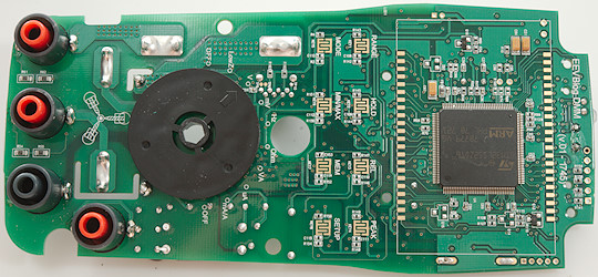
The schematic can be downloaded from EEVBlog for this meter, but I will add some explanation anyway.
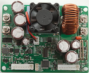
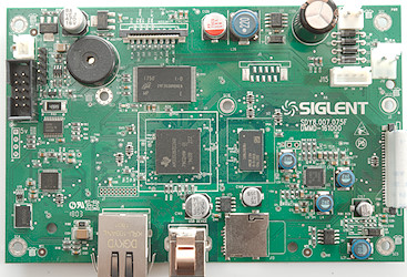
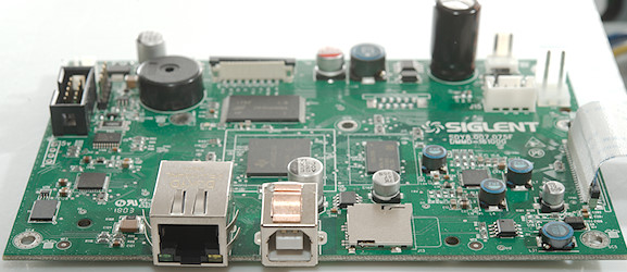
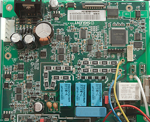
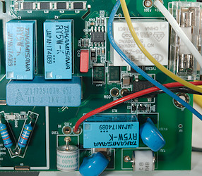
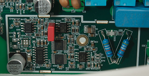
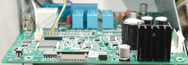
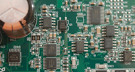
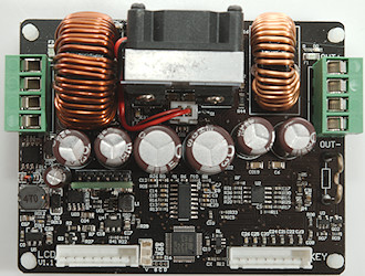
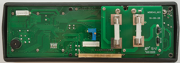
The current input has the usual 3 shunts, one wire and two resistors (R43, R33: 1ohm, 100ohm), but to get the low burden voltage there is a OpAmp (U8: MAX4238) with 10 times amplification next to the shunts, that is used for some current ranges. As usual the uAmA input is protected by a diode bridge (BD1) and due to the low burden voltage it do not need an extra diode. The detection of plugs in the current terminals goes to a dual OpAmp (U5: TL272C).
At the voltage input is a lot of PTC’s, there are the two input paths (PTC, PTC4) with series resistors )R16 & R17: 1kOhm) and MOVS (MOV1, MOV2, MOV3) and then there is the LowZ path with two PTC’s (PTC1 & PTC2) in series. The input resistor (R11: 10Mohm) is ceramic and there is a frequency compensation next to it (R9: 30kOhm, C13: 6pf) that can optionally be used. The meter has one transistor pair for protection (Q3 & Q5) and there is space for one more (Q1 & Q2), but there a transient diode (D13) is used instead)
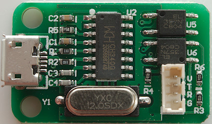
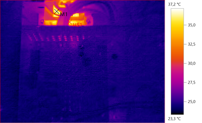
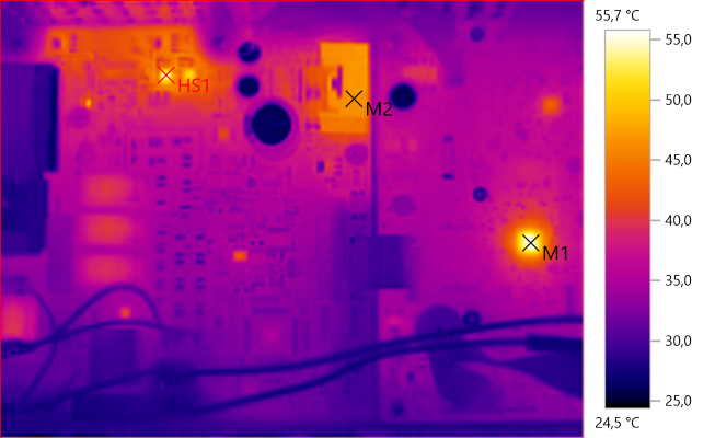
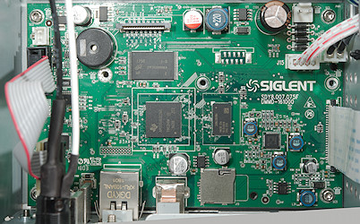
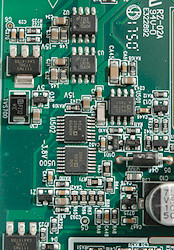
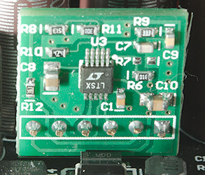
Generally there are many multiplexers on the board (U9: HJ4053, U11: HC4053, U15:HC4052, U16:HEF4053). The 15V boost converter (U10: RT9271) is near the top of the circuit board,ear a SMD inductor (L1).
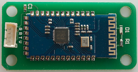
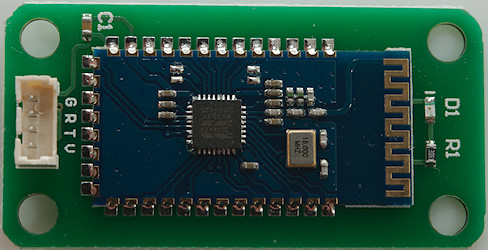
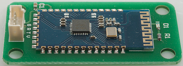
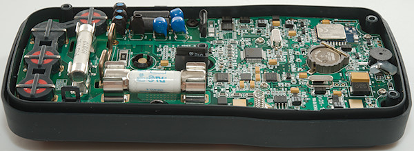
The multimeter chip (U3: HY3131) is close to the true RMS converter (U17: AD8436), there is also a reference in the area (ZD1: ADR3412). The bluetooth interface is a module (U6: BLE112). Near the buzzer is some hut melt glue, it secures a watch crystal for the RTC (U7: NJU6350R), this device is powered from the coin cell (CR1220) when the meter is off.
Image may be NSFW.
Clik here to view.
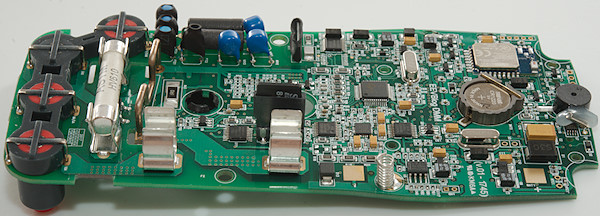
Image may be NSFW.
Clik here to view.
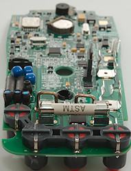 Image may be NSFW.
Clik here to view.
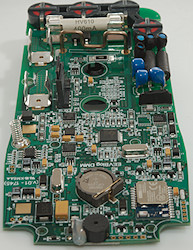
Image may be NSFW.
Clik here to view.
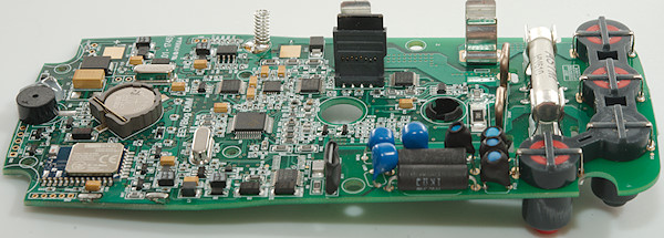
Image may be NSFW.
Clik here to view.
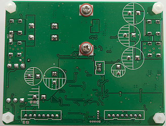
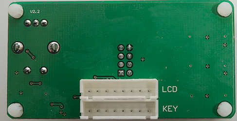
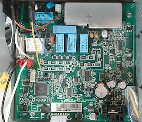
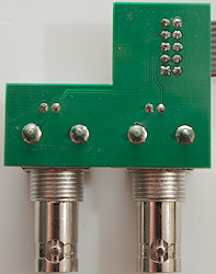
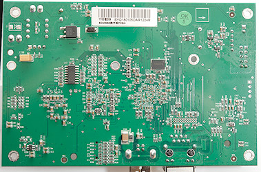
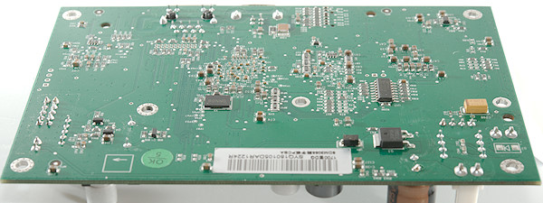
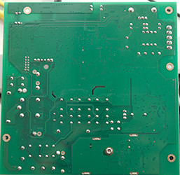
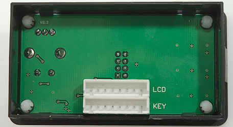
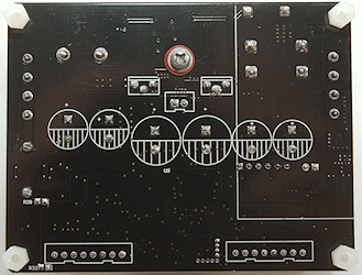
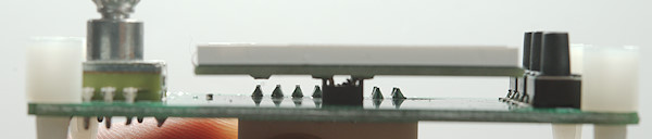
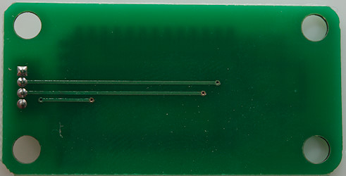
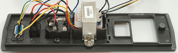
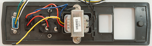
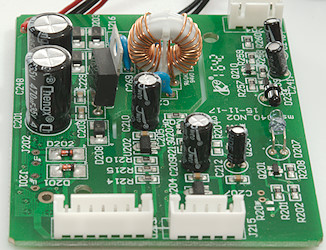
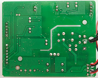
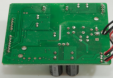
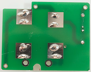
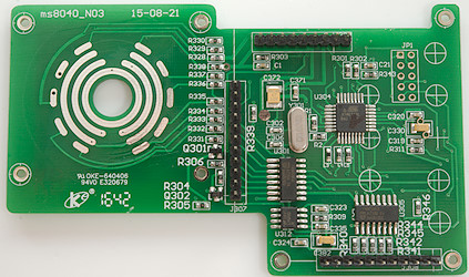
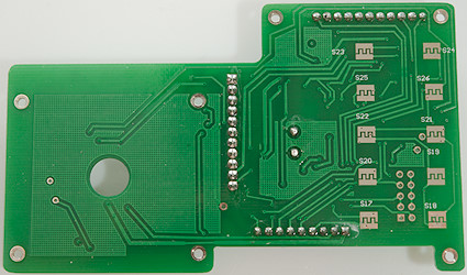
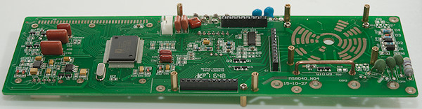
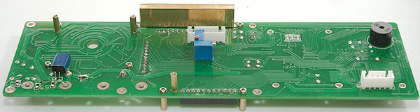
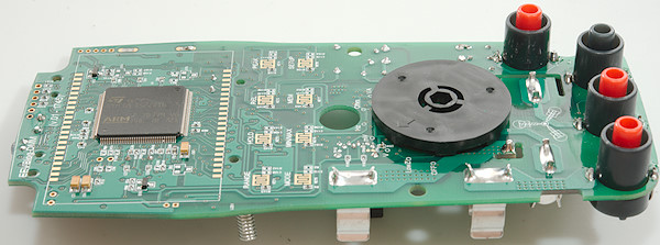
This side has the current terminals detection input (R51, R52, R54, R55: 4×4.7Mohm) from the split terminals, it has the pads for the rotary switch, the buttons and the LCD and it has the microprocessor (U4: STM32L152ZDT6 ARM Cortex-M3, 384k flash, 48k ram, 12k EEPROM)
Image may be NSFW.
Clik here to view.
Conclusion
It is an fairly advanced meter with some unusual functions like: 15V diode test, low burden voltage, VA measurement, SD card.
The meter has all the standard function for a good multimeter and also has all the common functions for a advance multimeter like: Bargraph, dual-display, average, peak, auto hold, logging, Bluetooth.
All this may sound like the perfect meter, but there are a couple of issues (There is a thread on EEVBlog), some of them will probably be fixed with software updates other is due to the design. The low burden voltage means a offset in some current ranges (Can be removed with REL). The meter is also a bit on the slow side.
For me the two most interesting functions are 15V diode test and low burden voltage, because I do not have them on other meters. The VA is fine for some DC measurement, but cannot measure AC power.
Notes
I got this meter from a Kickstarter campaign, as is often the case there was some extra delay, in this case about 4 months for second batch.
EEVBlog 121GW here is manuals, schematic and sale of the meter (when in stock).
The meter used firmware version 1.22 and during review I found a few issues, I reported some of them them to EEVBlog.
How do I review a DMM
More DMM reviews
My website with reviews of many chargers and batteries (More than 1000): https://lygte-info.dk/