Quantcast
Channel: BudgetLightForum.com - Gear Reviews
Viewing all 227 articles
Browse latest View live

Test/review of DMM DMM Peakmeter MS8229
$
0
0
Forums: 

DMM Peakmeter MS8229

DSC_2767

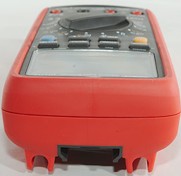
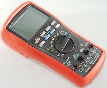
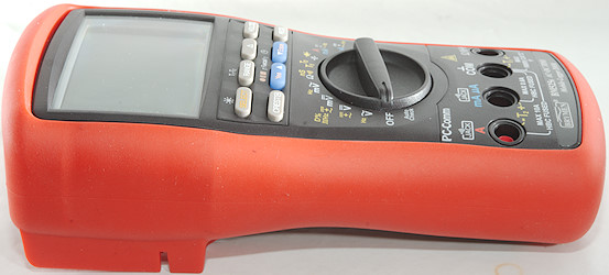
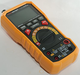
This is a cheap DMM with all common function and some environment functions.
DSC_2390DSC_2391DSC_2392DSC_2393

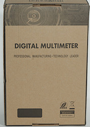
It arrived in a generic DMM box with no information on it.
DSC_2757

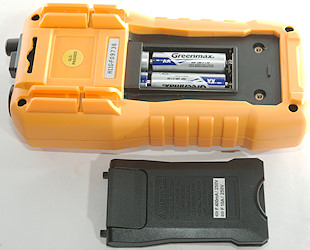
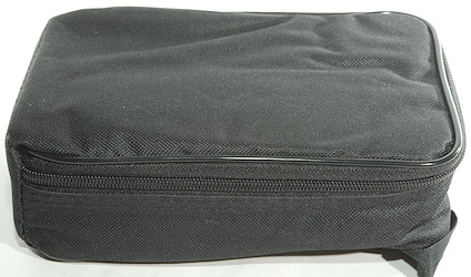
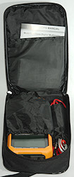
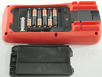
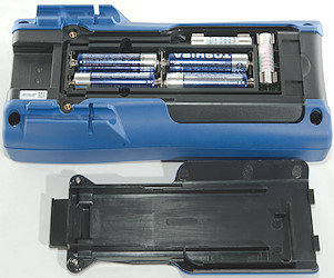
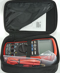
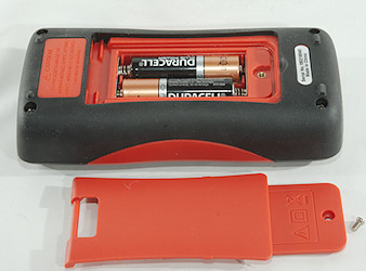
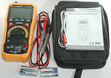
It included the DMM, a pair of probes, a thermocoupler, batteries, a bag and a manual.

DSC_2760
DSC_2761

The probes has removable tip covers. The CAT rating is marked on the tip and will change when the cover is removed.
DSC_2825

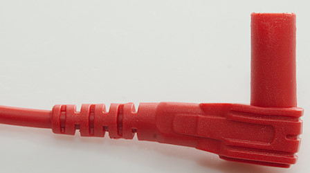
The plug is fully shrouded and a bit shorter than standard size.

DSC_2758
DSC_2759

The meter includes a cheap thermocoupler.
DSC_2764DSC_2768

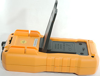
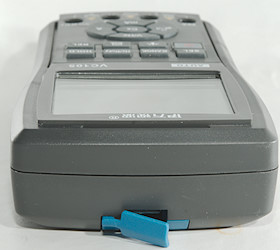
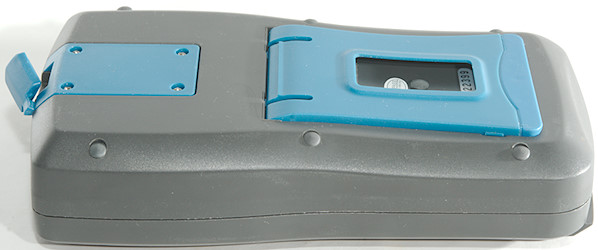
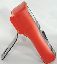
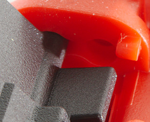
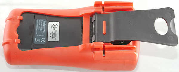
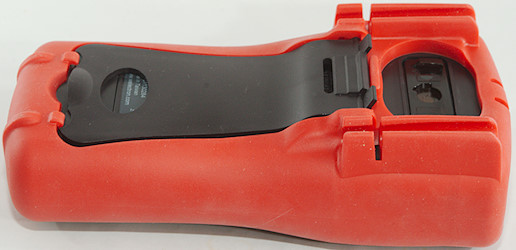
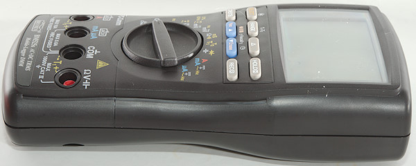
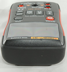
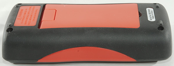
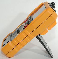
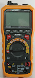
The tilting bale is stable enough to use the switch and buttons.
The range switch has very loud clicks, this can avoided by turning it carefully.
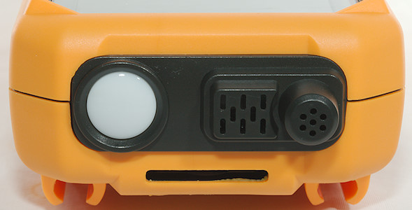
DSC_2766

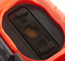
The environment sensors.

DSC_2762
DSC_2763

DSC_2754DSC_2774


Display

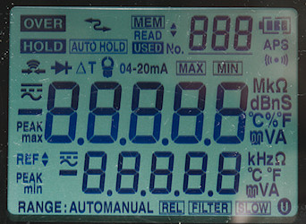
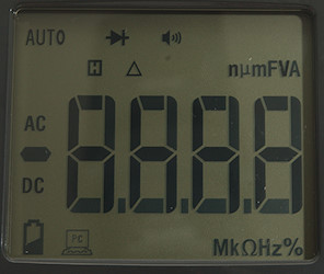
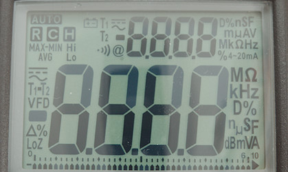
The meter do not show all segments during power on.
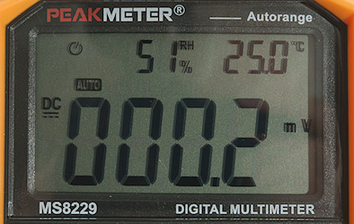
DSC_2770

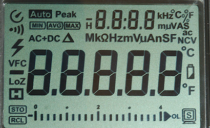
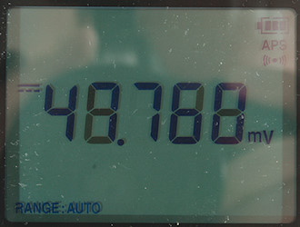
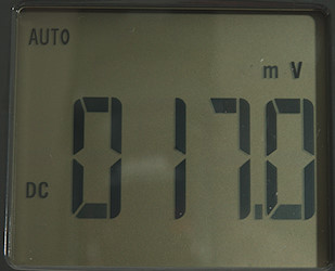
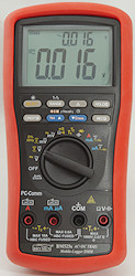
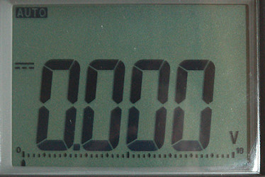
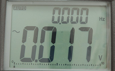
Typical display during usage, it will show the number and what measurement is selected.
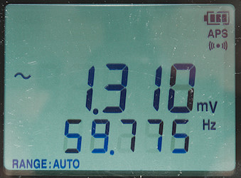
The display will always show humidity and ambient temperature, but they need a few second to initialize when powering on.


Functions
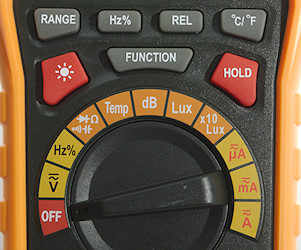
DSC_2771

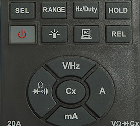
Buttons:


  • Range: Will disable auto range and change range, hold down to activate auto range again.
  • Hz %: Shows frequency and duty cycle in V and A ranges, changes to duty cycle in Hz range.
  • Rel: Shows values relative to current value, will also select manual range. Press again to disable.
  • °C/°F: Select between Celcius and Farnheit, holding this button down during power on will disable auto power off.
  • rangeBackground: Turn background light on.
  • Function: Select the secondary ranges (VAC AAC, continuity, diode, capacitance).
  • Hold: Freezes the display, press again to release.

Rotary switch:

  • Off: Meter is turned off
  • V: Voltage DC and AC, use FUNCTION to select AC and use manual range to select mVAC
  • Hz %: Frequency and duty cycle, for high bandwidth this selection must be used, it is only for low voltage.
  • rangeOhm: Ohm, Diode, continuity and capacitance range, use SELECT to change between them.
  • Temp: Temperature with thermocoupler, this will be shown on the main display and will not affect readout of ambient temperature.
  • dB: Sound pressure.
  • Lux: Brightness
  • x10Lux: Brightness, higher range. The display has a small x10 indication to show this range is selected.
  • uA: Current AC and DC, use SELECT to select AC
  • mA: Current AC and DC, use SELECT to select AC
  • A: Current AC and DC, use SELECT to select AC


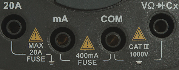
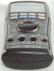
Input
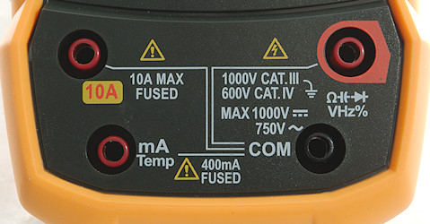
DSC_2772


  • 10A: High current, it can only withstand 10+ ampere for a short time (Fuse is 10A).
  • mAuA: The lower current ranges and thermocoupler (temperature) input, the selector switch will change between two different shunts, it has a 400mA fuse.
  • COM: The common terminal for all ranges.
  • xxx: All other ranges.


Measurements

  • Volt and frequency

    • Frequency counter and duty cycle requires a zero crossing on AC and DC range, frequency input do not require it, but only works with positive signals.
    • At 1Vrms frequency input range is from 0.4Hz to 700kHz
    • Input impedance is 9.3 to 11Mohm on DC and AC
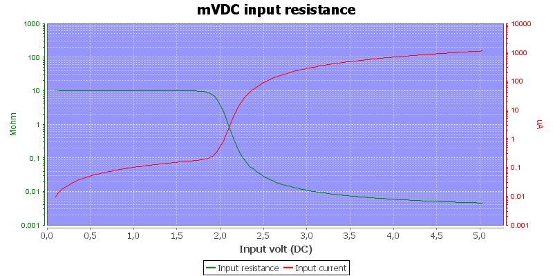
    • mVDC range is high impedance (100Mohm) up to 1.5V where it drops to 10Mohm
    • Duty cycle works from 10% to above 95% at 10kHz with 4Vpp, precision is within 3.6
    • Duty cycle is slow to stabilize.
    • 1 VAC is 5% down at 1.75kHz
    • High DC voltage may block for AC readings and vice versa.
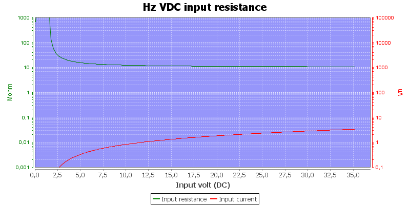
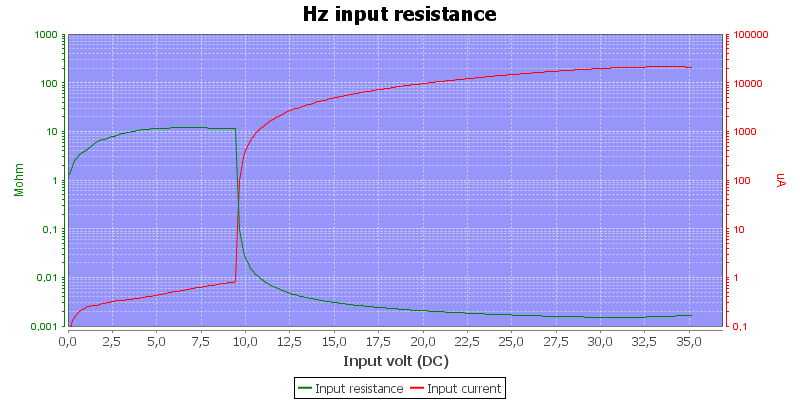
    • Frequency input is 1-10Mohm below 10V, above 10V it drops to 1.5kOhm

  • Current

    • mA range is protected with 0.4A/250V 6.3×32mm fuse
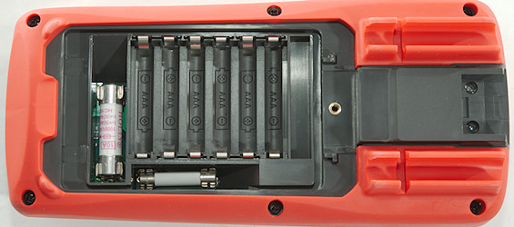
    • A range is protected with 10A/250V 6.3×32mm fuse

  • Ohm, Continuity, diode and capacity

    • Ohm needs about 2.8s to measure 100ohm
    • Ohm is 0.42V open and 0.21mA shorted
    • Continuity is moderate in speed (About 60ms).
    • Continuity beeps when resistance is below 44ohm (There is some noise for a few ohms more).
    • Continuity is 0.44V open and 0.21mA shorted
    • Diode range uses 1.5V, max. display is 0.999V at 0.2mA, max. current is 0.64mA shorted
    • 100uF takes about 16 seconds to measure.
    • 10uF takes about 3.2 seconds to measure.

  • Miscellaneous

    • Sound meter do not follow a A or C curve and readings will be too low at 1000Hz and above
    • Light meter is fairly precise with incandescent, but is not filtered correctly.
    • Meter will often reset when turning the switch, it will reset the display to Celcius.
    • Current consumption of meter is 4 to 5mA (15mA with backlight)
    • Meter turns off at 3.8V on battery, battery symbol show at 4.8V.
    • Reading will change slightly with battery voltage: 2 count on a 3.0V reading from 6V to 4.8V, below 4.8V %RH will increase slowly.
    • Backlight brightness will vary with voltage, but is works down to the meter turns off.
    • The meter usual need a couple of display update to reach the final value and may show a too high value during that time.
    • Viewing angle is fairly good, except from the top
    • Display updates around 3 times/sec
    • Backlight will automatic turn off in about 8 seconds.
    • Will automatic turn power off in about 10 minutes.
    • Standard probes fits in sockets.
    • Weight is 422g without accessories, but with rubber sleeve and batteries.
    • Size is 192 × 93 × 55mm with rubber sleeve.

  • Probes

    • Probe resistance 43mOhm for one.
    • Probe wire is soft and 100cm long.


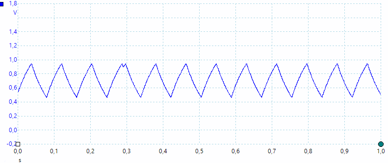
1uF

A look at the capacity measurement waveform.
DMMInputVoltageSweepHz

Frequency input resistance.

DMMschema

There is a 5° offset with thermocoupler when it is at zero.


Tear down
DSC_2858

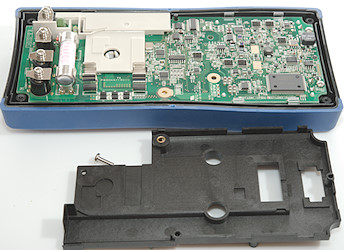
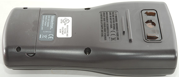
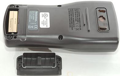
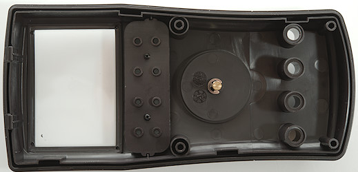
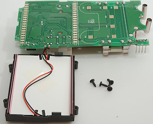
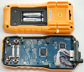
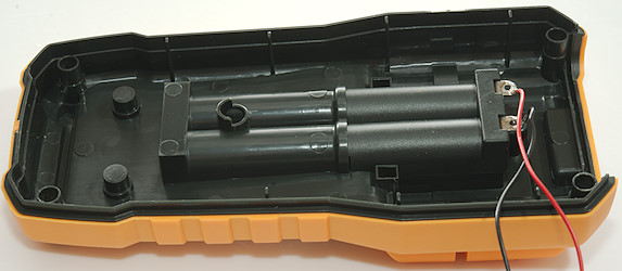
Four screws and the back could be removed.
DSC_2860

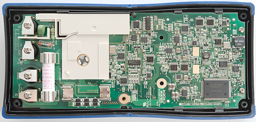
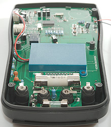
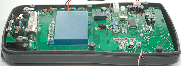
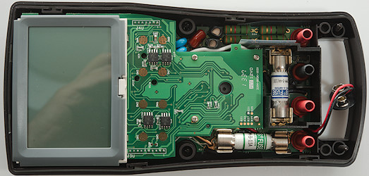
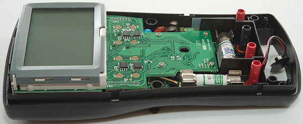
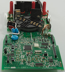
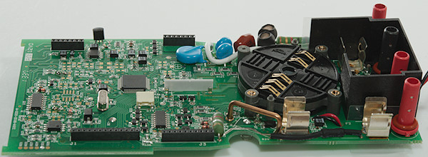
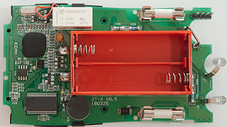
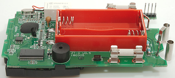
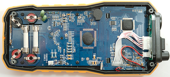
The circuit board is shaped to use the box fairly well. There is four screws holding the circuit board and 3 screws holding the display.
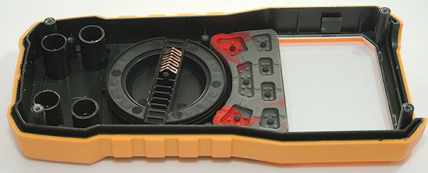
DSC_2866

DSC_2867

DSC_2861

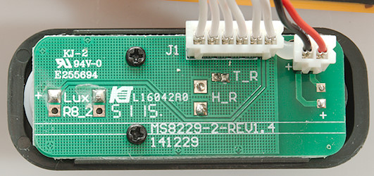
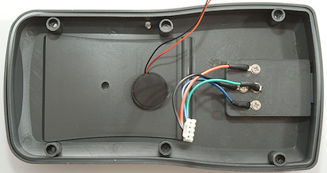
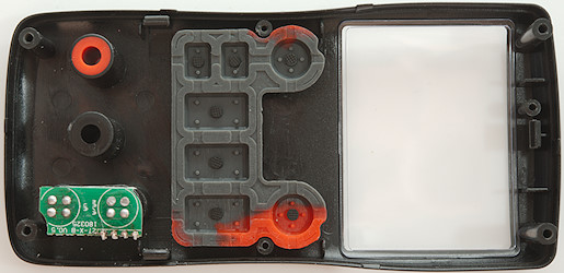
The sensors on the front uses two cables, one for lux, temperature and humidity and another for sound.
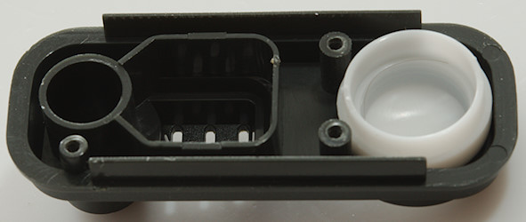
DSC_2863

The top of the meter with holes for the sensors.
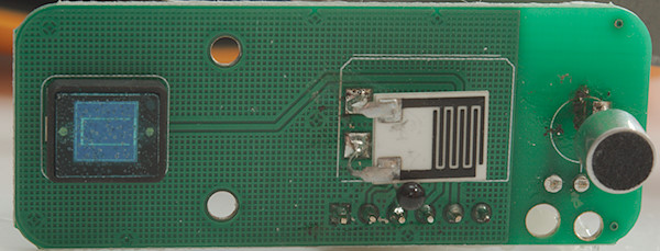
DSC_2862

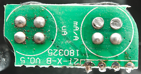
All four sensors, a photo diode, a humidity sensitive resistor, a temperature sensitive resistors and a microphone.
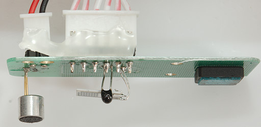
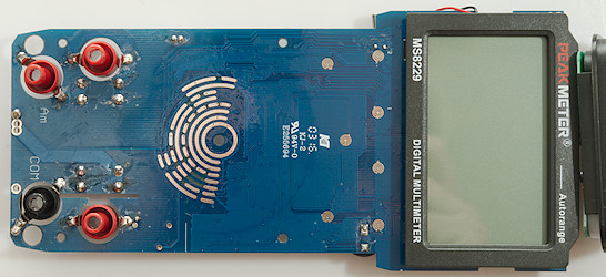
DSC_2864

DSC_2869

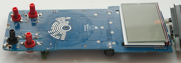
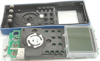
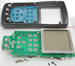
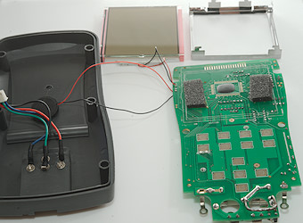
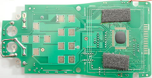
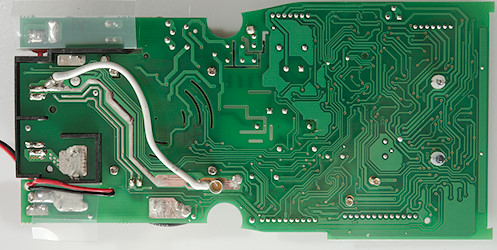
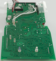
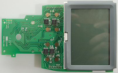
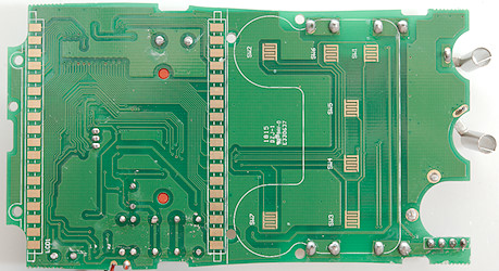
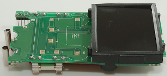
On this side of the circuit board is the switches and the lcd display.
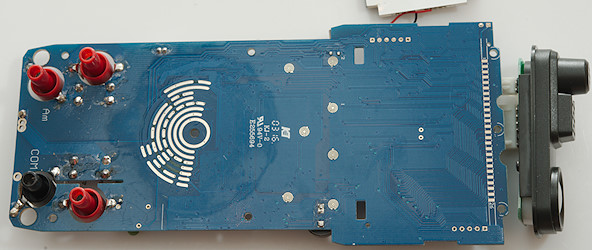
DSC_2870

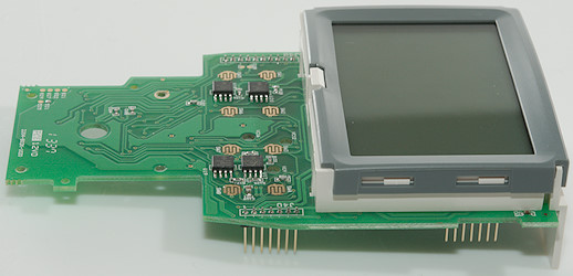
There is nothing under the lcd display, except the backlight module.

DSC_2871

DSC_2872

The white block is the backlight module, the pink part is the zebra stribe that connects the display to the circuit board.
DSC_2873

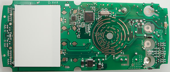
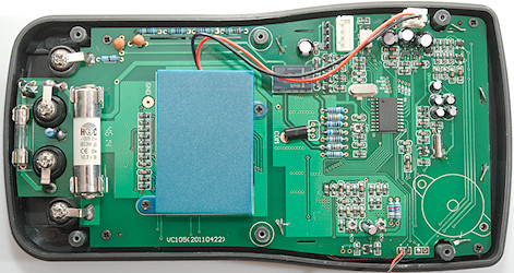
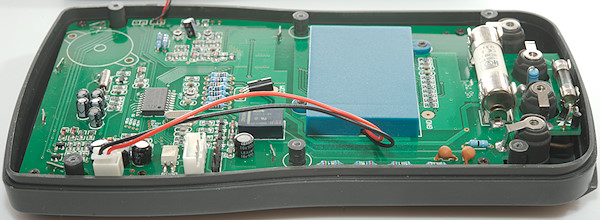
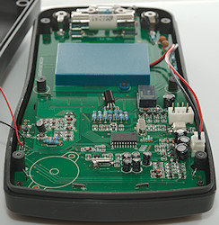
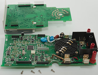
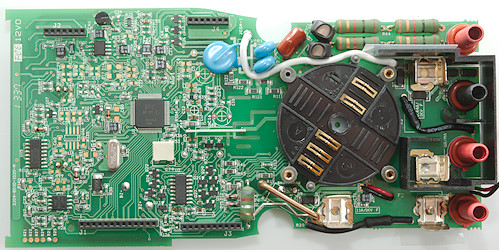
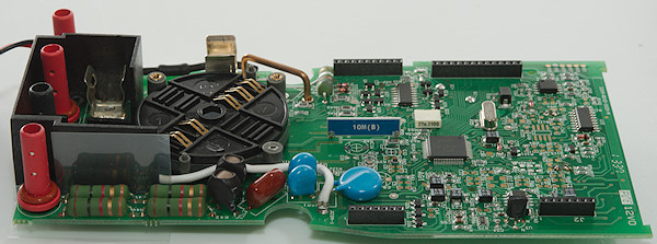
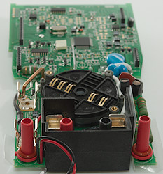
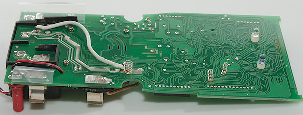
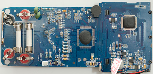
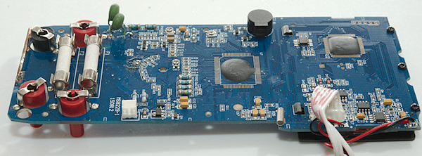
R63 is the 99ohm uA shunt and R66 is the 0.99ohm mA shunt, the chip near the resistors (VR1: 7530-1) is a 3 volt regulator. The 10A shunt is the wire at the bottom. The fuses are rated for 1000V and are the long type. But I am missing protection for the current sense resistor, this will usual be a couple of diodes.
At the voltage input is two PTC’s one going to a 10Mohm input (R37+R38: 2×5Mohm) and on going to a 150Mohm input (R80, R81, R82: 3×47M). The transistors Q7 and Q9 looks like input protection. There is no MOV’s to limit the voltage to the range switch.
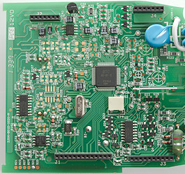
The meter has two main chips: U7 is the DMM frontend and U2 is the processor, U1 is probably a EEPROM, the 3 trimpots on the circuit board is not enough to trim all the ranges. The handling of the environment sensors are U4, U5 and U6, all placed where the wires from the sensors are connected.
DSC_2874


Conclusion

As usual I doubt the CAT rating, this meter do have some protection, but not enough. The environment sensors can be used, but sound is very bad and light is probably about the same as a cheap lux meter, except it only has two ranges.
The DMM functions are fairly standard, as usual the high mA range has a high burden voltage.


Notes

How do I review a DMM
More DMM reviews

My website with reviews of many chargers and batteries (More than 1000): https://lygte-info.dk/


Test/review of Internal Resistance Tester YR1035

$
0
0
Forums: 

Internal Resistance Tester YR1035


DSC_7156

This is a meter designed to measure internal resistance in batteries.

DSC_7146

I got the meter in a random shipping cardboard box, it contained:
The meter, 4 terminal probes with extra pogo pins, 4 terminal clamps, 4 terminal battery holder and a manual in Chinese (It is possible to order with the accessories that you want).

DSC_7155

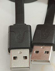
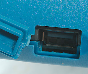
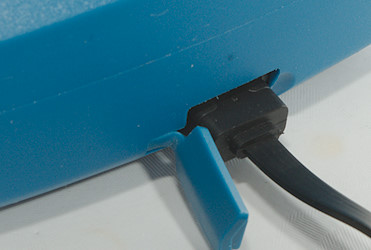
The meter has a recharge battery inside and is charged from a micro usb connector.

DSC_7160

It uses a round metal connector for the four terminal connection. The connector is locking, i.e. the plug cannot fall out. Pulling the ring on the plug will unlock it can be pulled out.

DSC_7161

DSC_7162DSC_7163

DSC_7410

The meter has Chinese text in the display and it is not possible to select English.

DSC_7409

For just using it as a milli-Ohm meter it is not really an issue.

DSC_7398

When not used for some time, it will go into standby mode, this requires a button pres to leave.

DSC_7414


There is a couple of buttons:
Power is used to turn on/off the device.
Hold/Zero is used to freeze the ohm reading, I did not have much luck with the zero function.
Range R is used for manual range select on ohms (20m, 200m, 2, 20, 200, auto).
Range U is used for manual range select for volts (1V, 10V, 100V, auto).

DSC_7148

Four terminal probes made with pogo pings in aluminium tubes and some shrink wrap.
The wires are soft silicone.

DSC_7150

A closer look at the business end.

DSC_7147

If a pogo pin is damaged, it can be pulled out and a new one pushed in, the pack included four spares.

DSC_7149

The plug looks like a fairly good quality.

DSC_7151

The clamps are a cheap Chinese four terminal model.

DSC_7152

The battery holder is a fairly standard four terminal holder (I use same type for my battery test). It is not the fastest way to connect a battery, but gives stable connections.


Measurements


  • The ohm meter is 2200 count display
  • The voltmeter is a 100000 count display.
  • The AC used to measure ohms are 1kHz at up to about 100mV rms, it will vary with range and measured resistance.
  • Output voltage when open is about 2.5Vrms.
  • Power consumption while off: 5.1uA
  • Power consumption while on with light: 65mA
  • Power consumption while on with light and shorted probes: 140mA
  • Power consumption in standby mode: 15mA


ohm

Due to the way the meter works it do not need a battery to measure resistance, but can be used as a general milliohm meter.
Here I am testing on some resistors and comparing to a very precise meter.
The precision is very good.

volt

The same with voltage, again the precision is very good and it has lots of digits.

10ohm

The meter is using a 1000Hz sinus for measuring the resistance

21.9ohm

The maximum AC voltage is about 30mVpp when measuring 22 ohm.

220ohm

The maximum AC voltage is about 300mVpp when measuring 220 ohm.

unloaded

With unloaded outputs the voltage will be considerable higher at about 5.3Vpp


Tear down

DSC_7415

I had to remove four screws to open the box.

DSC_7416

it is a standard project box with some machining and a custom frontplate.

DSC_7417

The circuit is on two circuit boards, one for the display and one for everything else. The used battery is a LiIon 18350 cell marked with 900mAh.

DSC_7418

Four more screws and I could remove the circuit board.

DSC_7425

Markings has been carefully removed from nearly all the chips.

DSC_7419

DSC_7420DSC_7422

DSC_7421

DSC_7423
DSC_7424

DSC_7426DSC_7427

Before removing the display board I unsoldered the battery (Only one connection).

DSC_7428

There are two mechanical relays and space for a usb interface chip (U7). There is 5 trimpots to calibrate it with.

DSC_7429


Conclusion

This milli-ohm meter is very good and can both be used to measure internal resistance in batteries and to measure small resistors with. Because it uses AC it will give too high reading on anything inductive, but measuring resistors and small metal pieces works fine.

When using it as a milli-ohm meter the Chinese text is not a big problem, but it is a bit tricky to change any options or use the more advanced functions.


Notes

As reference I used my Keithley DMM7510, it can do 4 terminal ohm measurement.

Vapcell Internal Resistance Tester YR1030
Internal impedance/resistance of batteries

My website with reviews of many chargers and batteries (More than 1000): https://lygte-info.dk/

Test/review of DMM Aneng AN870

$
0
0
Forums: 

DMM Aneng AN870

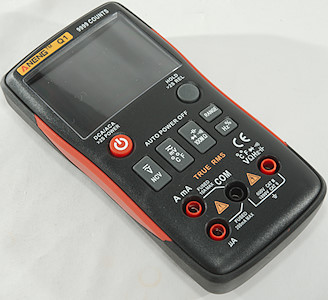
DSC_7470

The brand Aneng has been on a lot of meters recently (in 2017), most of them very capable meters at very good prices, do this trend continue with this meter?

DSC_7454

I got the meter in the usual black plastic bag with some protective wrapping around the pouch.

DSC_7455DSC_7456

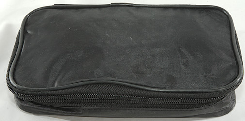
The pouch.

DSC_7458

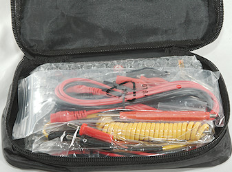
It included the DMM, a pair of normal probes, a pair of DIY probes, a thermocoupler and a manual.

DSC_7467
DSC_7468

The probes has removable tip covers, the tip and tip cover has the usual CAT markings, but there is not much markings on the probe them.

DSC_7469

The shrouded plug is the slightly short variety.

DSC_7491

The DIY probe set, it is a bit low in quality and some work may be required to screw the tips in (One of the banana plugs was missing threads).

DSC_7490

A end without any tip.

DSC_7459
DSC_7460
DSC_7461
DSC_7462
DSC_7463

The DIY probes with the different tips.

DSC_7464
DSC_7465
DSC_7466

The thermocoupler is the probe type, this is useful for stuff where you want to stick the thermocoupler in, but not very good at measuring surface temperatures.


DSC_7475DSC_7484

The range switch is a bit difficult to use single handed when meter is on the tilting bale, it slides around.

DSC_7471DSC_7473

DSC_7472

DSC_7474

DSC_7476

DSC_7477

DSC_7478

DSC_7479DSC_7481

DSC_7480

DSC_7482


Display

DSC_7506

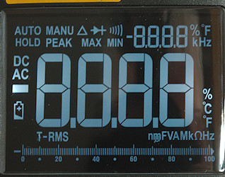
The above picture shows all the segments on the display, not all are used by this meter.
Notice the small 2, 20,200, 2000 digits, they are used to show the selected range.
The backlight has a hotspot at the minus sign, the rest of the display is fairly even illuminated.

DSC_7507

Typical display during usage, it will show the number and what measurement is selected.

DSC_7487

The NCV is the usual bars and the buzzer.


Functions

DSC_7488

Buttons:


  • Range: Will disable auto range and change range, hold down to activate auto range.
  • Rel: Shows values relative to current value, will also select manual range. Press again to disable.
  • Max/min: Starts recording maximum and minimum value, press to select between max/min.
  • Hz % (Blue): Shows frequency and duty cycle in AC ranges.
  • Select (Yellow): Select the ranges printed with yellow and between C°/F°
  • Hold: Freezes the display, hold down for backlight.

REL and MAX/MIN will change to manual range and return to auto range when disabled.

Rotary switch:

  • Off: Meter is turned off
  • VAC: Show AC voltage, using the blue button frequency and duty cycle can be selected.
  • VDC: Show DC voltage.
  • mV: Show DC or AC mV and temperature. In AC the blue button will show frequency and duty cycle.
  • ohm: Resistance, continuity, diode and capacity.
  • Hz: Logical frequency and duty cycle (Use blue button to change between them).
  • A: Current AC and DC. In AC the blue button will show frequency and duty cycle.
  • mA: Current AC and DC. In AC the blue button will show frequency and duty cycle. Watch out for burden voltage.
  • uA: Current AC and DC. In AC the blue button will show frequency and duty cycle.
  • NCV: Non-contact voltage or electric field detection.


Input

DSC_7489


  • 20A: High current, it can only withstand 20+ ampere for a short time due to heat (Fuse is 20A).
  • mAuA: The lower current ranges, the selector switch will change between two different shunts (Fuse is 200mA).
  • CON: The common terminal for all ranges.
  • xxx: All other ranges.


Measurements

  • Volt and frequency

    • At 100mVrms input frequency range is from 1Hz to 5.6MHz
    • At 2Vrms input frequency range can be stretched to 20MHz
    • Max/min needs about 360ms to capture a voltage with repeating pulses.
    • 1 VAC is 5% down at 2.1kHz (RMS will not work at the frequency).
    • Frequency counter and duty cycle can only be selected in AC ranges.
    • Frequency input requires a zero crossing.
    • Duty cycle works from 2% to above 99% at 100kHz with 1Vpp, precision is within 0.2 (Mostly 0.1).
    • Input impedance is 10..11Mohm on DC and AC
    • mV range is high impedance for DC up to around 1.5 volt where it drops to a few kOhm. AC is similar, but capped at 10Mohm
    • Frequency input is 10Mohm up to around 2 volt, then the protection clamps to 2kOhm

  • Current

    • Frequency counter and duty cycle can only be selected in AC ranges.
    • 200mA current is protected by a 0.2A/250V 6×30mm fuse.
    • 20A current is protected by a 20A/250V 6×30mm fuse.
    • The 20A range has an audible alarm at 10A.

  • Ohm, Continuity, diode and capacity

    • Ohm needs about 2.8s to measure 100ohm
    • Ohm is 1V open and 0.37mA shorted
    • Continuity is fast (About 20ms).
    • Continuity beeps when resistance is below 50ohm.
    • Continuity is 1V open and 0.37mA shorted
    • Diode range uses 3.2V, max. display is 3.000V at 0.13mA, max. current is 1.6mA shorted
    • 10uF takes about 4.5 seconds to measure.
    • 70000uF takes about 9 seconds to measure.
    • Overload protection is not rated

  • Miscellaneous

    • Current consumption of meter is 1.2 to 2mA depending on range (AC adds 0.4mA), with backlight it is up to 9mA.
    • Meter works down to 2.2V where it turns off, battery symbol show at 2.4V.
    • Reading do not change with battery voltage.
    • Backlight only works down to about 2.6V where it is fairly dim.
    • The meter usual need a couple of display update to reach the final value.
    • Viewing angle is good.
    • Display updates around 3 times/sec
    • Backlight will automatic turn off in about 120 seconds.
    • Will automatic turn power off in about 15 minutes.
    • Standard probes cannot be pushed fully down they are a bit loose.
    • Weight is 374g without accessories, but with rubber sleeve and batteries.
    • Size is 180 × 89 × 44mm with rubber sleeve.

  • Probes

    • Probe resistance 33mOhm for one.
    • Probe wire is soft and 78cm long.
    • DIY probes resistance is 51mOhm
    • DIY probe wire is 86cm long


1uF

A look at the capacity measurement waveform.

DMMInputVoltageSweepHz

Frequency input resistance depends on input voltage. This is fairly similar to mVAC input.

DMMschema

The meter cannot be used at 20A, the reading will drift (At 19A 5% drift in 13 seconds). At 10A the drift is still present, but much slower.
AC input cannot handle large DC offset.


Tear down

DSC_7492

Four screws and the back could be removed.

DSC_7493
DSC_7494

The circuit board is shaped to follow the box.

DSC_7495
DSC_7496

6 small screws and the circuit board was nearly loose, I had to unsolder the backlight to get it out.

DSC_7497

The display and backlight are still in the box-

DSC_7498

DSC_7500

The 20A shunt (R33: 0.01ohm) is very small, it is no wonder it cannot handle 20A without getting hot, or is it the copper trace. Sense is connected to the uA shunt (R23: 99ohm). The mA shunt (R24: 1ohm) is next to the uA shunt. On opposite side of the circuit board is the mAuA fuse and a transient diode (D5: 6V8) to protect the resistors until the fuse blows.
The 10Mohm input is done with two resistors (R29 & R30: 2×5Mohm) and goes directly to the chip. For the ohm, capacity, frequency and mV input the input goes to a PTC (PTC1: 1.5Kohm) and a transistor pair (Q3 & Q4).
The multimeter IC (IC3) has a external EEPROM (IC1: P24C02A) for calibration and functions, there is also a reference IC (Q5: ICL8069). There is a transistor for the buzzer (Q2) and for the backlight (Q1).
At the top of the circuit board is a trace as antenna for the NCV, it has some high ohmic resistors (R37, R38, R39: 3×20Mohm) as load.

DSC_7501

DSC_7502DSC_7504

DSC_7503

DSC_7499

This side of the circuit board only has contact pads for the switches, range selector and LCD display. The 20A trace is also present in this side, but it is not enough for 20A.


Conclusion

The meter is within the specified tolerances (Except 20A range) and it has lot of functions and ranges, but the CAT rating is fake.
It is a fairly good meter to use on the bench.


Notes

The multimeter was supplied by Banggood for review.

How do I review a DMM
More DMM reviews

My website with reviews of many chargers and batteries (More than 1000): https://lygte-info.dk/

Test/review of DMM UNI-T UT120C

$
0
0
Forums: 

DMM UNI-T UT120C

DSC_6538

This is a small pocket DMM with voltage, current, frequency, ohms and capacity.

DSC_6492DSC_6493

The meter was in a clamshell pack. On the back is a comparison between the 3 models in this series, this one here is the only model with current and mVDC.

DSC_6534

In the pack was the meter and a manual in English.

DSC_6544

The probes are small, but they are rated for 600V.

DSC_6551DSC_6553

The probes are directly connected to the meter, no plugs and sockets. The meter can be used inside the box, this will give some splash protection.

DSC_6549

The range switch is easy to turn, but the detents are not very marked, it is easy to place it between ranges.

DSC_6868DSC_6869
DSC_6870
DSC_6539
DSC_6540
DSC_6545
DSC_6546


Display

DSC_6547

The above picture shows all the segments on the display.

DSC_6548

Typical display during usage, it will show the selected range and value.


Functions

DSC_6550

Buttons:


  • Select: Select AC in volt and current ranges and between ohm, diode, continuity and capacitance
  • Hz/duty: Will select between voltage, frequency and duty cycle in both DC and AC.
  • Rel: Store current display value and show all new values relative to this value.
  • Hold: Will freeze the display reading, until pressed again.

Selection of Rel and Hz/duty will disable auto ranging and it stays disabled

Rotary switch:

  • Off: Meter is turned off
  • V: DC/AC voltage and frequency/duty cycle.
  • ohm: Ohm, diode continuity and capacitance.
  • Hz: Logical frequency input.
  • uA: Microampere both AC and DC and frequency/duty cycle
  • mA: Milliampere both AC and DC and frequency/duty cycle


Input

DSC_6541

This meter only have a red and black probe coming out, no other connections.


Measurements

  • Volt and frequency

    • At 1V rms input on frequency the counter range is from 0.5Hz to 720kHz
    • At 2V rms input on frequency the counter range is up to 1.5MHz
    • At 5V rms input on frequency the counter range is up to 4.1MHz
    • Duty cycle works from 5% to 95% at 10kHz with 4Vpp, precision is within 3.0
    • Frequency inputs need a zero crossing.
    • 1V AC readings is 5% down at 2kHz
    • V input impedance is 10-11Mohm,
    • mV input impedance is high below 1.5V and drops to 100kOhm below 12V, above it drops to 2kOhm, AC is clamped by 10Mohm.
    • Frequency input is above 1Mohm below 8V and drops toward 1kohm above 12V
    • Input protection is 600V AC/DC.

  • Current

    • Fuse is a PTC

  • Ohm, continuity, diode and capacity

    • Ohm needs about 3.5s to measure 100ohm
    • Ohm is 0.42V open and 0.22mA shorted
    • Continuity is very fast (
    • Continuity beeps when resistance is below 20ohm and makes noises up to about 50ohm
    • Continuity is 0.44V open and 0.22mA shorted
    • Diode range uses 1.5V, max. display is 0.999V at 0.2mA, max. current is 0.67mA shorted
    • 100uF takes about 13 seconds to measure.
    • Rated overload protection is 600 VDC/VAC

  • Miscellaneous

    • Current consumption of meter is 1.4mA except DC where it is 0.8mA
    • Meter fails below 1.6V, battery symbol show at 2.4V.
    • Readings will drift about 8 count when from when battery symbols shows to the meter fails.
    • Viewing angle is good
    • Display updates around 3 times/sec
    • Will automatic turn power off after about 30 minutes
    • The meter often need many display update to reach the final value.
    • Weight is 62g without accessories (102g in plastic box), but batteries.
    • Size is 110 × 58 × 14mm (probes not included) and 121 × 90 × 18.3 in box.

  • Probes

    • Probe wire is a bit thin, they are 47cm long.


1uF

Capacity measurement waveform.

DMMInputVoltageSweepHz

Frequency input resistance in voltage frequency position.

DMMInputVoltageSweepHzVAC

Frequency input resistance in voltage AC position.

DMMschema

The meter cannot measure low AC volt when there is a large DC voltage.
Capacity has a 10nF offset, i.e. lowest range cannot be used, but meter is within specified tolerances. Lowest range is not specified and with REL the other are within tolerances.


Tear down

DSC_6545

I had to remove one screws, to open it, this is also required when replacing battery.

DSC_6871

DSC_6872

Four clips to get the circuit board out, I did also remove the screw to the range switch, but that was not necessary.

DSC_6873

The bizzer is placed behind the lcd display and the connection is made with some springs on the circuit board. The display uses a zebra stribe as usual.

DSC_6874

DSC_6876

This meter requires a lot of adjustment from the factory (VR1..VR4: Trimpots). On the input side we have a PTC for protection in ohm and frequency ranges, the ohm sense input (R19: 900kOhm), the 10Mohm input (R26 & R28: 2×5Mohm). There is also 3 protection transistor pairs (Q1 & Q2, Q3 & Q4, Q5 & Q6). R19 uses Q3 & Q4 as protection. PTC uses Q5 & Q6 in ohms and Q1 & Q2 in frequency.
Current shunts (R16: 1ohm, R17: 99Ohm) are protected by diodes (D5, D6, D8, D9) and the large PTC (PPTC2).

DSC_6877

DSC_6878DSC_6880

DSC_6879

DSC_6875

This side is without parts, but some stuff on the other side needs holes in the circuit board.

DSC_6881

DSC_6882

From this side the 3 springs to the buzzer can be seen.


Conclusion

The meter says CAT II 600V, if the range switch can handle 4000V without arching it may be correct.

The meter is well equipped with ranges for a pocket meter and can match many larger meters, precision is fairly good (Except low capacity range), safety looks decent for occasionally mains work at home.


Notes

How do I review a DMM
More DMM reviews

My website with reviews of many chargers and batteries (More than 1000): https://lygte-info.dk/

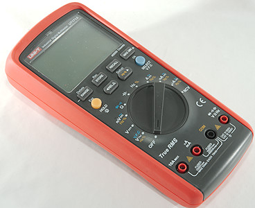
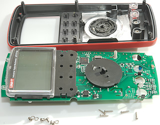
Test/review of DMM UNI-T UT171A

$
0
0
Forums: 

DMM UNI-T UT171A

DSC_6232

This is a industrial DMM designed with good precision and logging. It is the simplest meter in the UT171 series and uses AAA batteries, the other meters in the series has builtin LiIon batteries.

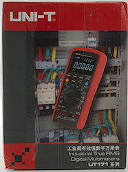
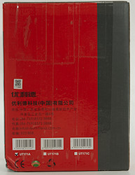
DSC_6217DSC_6218DSC_6219DSC_6220

The box do not say anything about the meter and the illustration is of another model in the UT171 series.

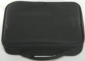
DSC_6221

Inside the box was only a pouch.

DSC_6222

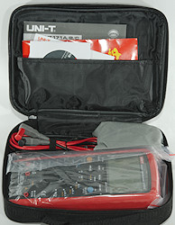
With all parts inside.

DSC_6224

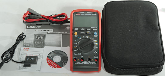
That was the meter, the probes, a CD with software and a manual (Both software and manual can be downloaded).

DSC_6229
DSC_6230

Probes are branded UNI-T and rated for 10A

DSC_6231

With a tip cover they are CAT IV 600V or CAT III 1000V, without CAT II 1000V (This is fairly standard for probes).

DSC_6982

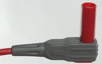
The plugs are fully shrouded, but the shroud is a bit short

DSC_6235DSC_6246

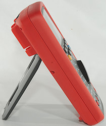
The meter is heavy enough to keep it stable while turning the range switch, this means it can easily be used with one hand, either lying flat or standing.

DSC_6233
DSC_6234

DSC_6236DSC_6237

DSC_6239

DSC_6238


Display

DSC_6252

All the segments are shown during power on, not all of them are used.

DSC_6251

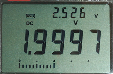
Typical display during usage, it will show the number and selected measurement

DSC_6254

During logging the secondary display will show remaining time of logging session (May alternate with other values).

DSC_6255

Here I have activated the max/min/avg function and the secondary display is used for these value, the main display will continue to show the input voltage.

DSC_6253

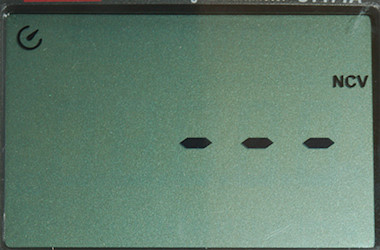
NCV display is the usual bars and a red flashing led above the display, together with the buzzer.

The secondary display is used for:


  • VAC/mVAC: Frequency/duty cycle
  • AAC/mAAC/uAAC: Frequency/duty cycle
  • Hz: Duty cycle
  • Min/max: Min/max/average
  • REL: Reference value
  • Range: Shortly shows selected range (4/40/400/4000 it is adjusted to the correct max value)
  • Logging: Remaining time
  • Recall: Record number in log.
  • Store: Prompt text
  • Setup: Parameter value, main display is prompt text.


Functions

DSC_6247

Buttons:

  • Range: Select manual range and change range, hold down to reactivate automatic ranging (I did not find any usage for Delete).
  • Store: Store a single value in the log, hold down to start recording (Meter will prompt for record interval and record time).
  • Recall: Press to recall last value from the log, use arrow keys to move around, end with Esc.
  • Max Min: Start max/min/average function, press to select readout in secondary display, main display will show actual value.
  • Hold/Esc (Yellow): Will freeze the display reading, until pressed again, hold down to activate backlight. When in configuration it is a escape button.
  • Rel: Shows values relative to current value, will also select manual range (Reference value is show in secondary display). Press again to disable.
  • Hz % Setup: Select frequency/duty cycle in AC voltage and current modes, hold down to enter configuration.
  • Ok Select VFC: Select AC in mV and current modes, hold down to activate LPF in VAC mode.

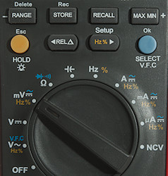
Rotary switch:

  • Off: Meter is turned off
  • VAC/VFC: AC voltage, hold blue button down to activate LPF (Low pass filter)
  • DCV: DC voltage
  • mV: AC or DC milli volt
  • ohm: Ohm, continuity and diode.
  • c: Capacitance.
  • Hz: Logical frequency input.
  • A: Ampere DC or AC
  • mA: Milli ampere DC or AC
  • uA: Micro ampere DC or AC
  • NCV: Non contact voltage, this is not very sensitive.


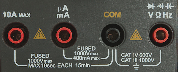
Input

DSC_6248


  • 10ADC: 10A DC current input.
  • uAmA: Micro and milliampere input.
  • COM: The common terminal for all ranges.
  • xxx: All other ranges.


Measurements

  • Volt and frequency

    • 1V AC readings is 5% down at 130kHz, rms will not work at that frequency
    • 7V AC readings in VFC is 5% down at 430Hz, rms will not work at that frequency
    • Frequency input do not require a zero crossing, it has a capacitor at the input.
    • At 0.1Vrms frequency input range is from 2Hz to 1MHz
    • At 1Vrms frequency input range is from 2Hz to 20MHz
    • At 3Vrms frequency input range is from 2Hz to 47MHz
    • Duty cycle works from 30% to 80% at 100kHz with 4Vpp, precision is within 6.0.
    • Duty cycle works from 20% to 91% at 10kHz with 2Vpp, precision is within 1.0.
    • Max/min needs about 280ms to capture a voltage, autorange is disabled when using this function.
    • Input impedance is 10-11Mohm on DC, AC has a capacitor in input.
    • mV AC/DC is 10Mohm below 2V where it drops to a few kOhm (Manual specify high impedance, but that is not correct).
    • Maximum voltage not specified.

  • Current

    • 10A range is fused with a 10A/1000V 10×38mm fuse
    • mAuA range is fused with a 0.8A/1000V 6×32mm fuse
    • Display will show “Lead” when leads are in the wrong terminal and the buzzer will sound if a current terminal is used when not expected.

  • Ohm, continuity, diode and capacity

    • Ohm needs about 0.8s to measure 100ohm
    • Ohm voltage is 1V open and 0.65mA shorted.
    • Continuity is quick (About 80ms).
    • Continuity beeps when resistance is below 15ohm.
    • Continuity is 2.1V open and 0.65mA shorted
    • Diode range uses 3.1V, max. display is 3.000V at 0.06mA, max. current is 1mA shorted
    • 10uF takes about 1.6 second to measure.
    • 11000uF takes about 8 seconds to measure.
    • Overload protection is not specified.

  • Miscellaneous

    • Current consumption of meter is 12mA (16mA with backlight at 50%).
    • Meter turns off at 6.8V, battery symbol show at 7.3V.
    • Readings will be correct until meter turn off.
    • Backlight is fairly stable until meter turns off
    • Viewing angle is good
    • The meter can log 1000 values, there is no concept of files, all values are saved in on long list.
    • Display updates around 5 times/sec
    • Bargraph updates faster than numbers.
    • Configuration: Auto power off, Auto backlight off, Erase log, Brightness, USB, Buzzer
    • Backlight can be configured in 5 to 30 seconds auto turnoff or never.
    • Power can be configured in 5 to 30 minutes auto turnoff or never.
    • Standard probes cannot be fully seated in the meter, but they do connect.
    • The meter usual shows the correct value at first update.
    • Weight is 515g without accessories, but with battery.
    • Size is 206 × 95 × 53mm

  • Probes

    • Probe resistance 30mOhm for one.
    • Probe wire are 88cm long.


DMMInputVoltageSweepmVDC

mVDC is high impedance up to about 2V.

DMMschema

The 40mA DCA range is 0.35% wrong, this is outside specified tolerance.
The 400mA DCA range is 0.39% wrong, this is outside specified tolerance.


Software on PC

DSC_6225DSC_6226

The software and usb cable for a computer connection is supplied. The software is on a mini CD (Can also be downloaded), it contains the software and a very basic manual for the software. The adapter is a HID device.

DSC_6227

The adapter is slided in at the top of the meter. Remember to enable usb in configuration each time the meter is turned on and you want to use usb.

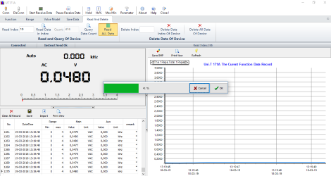
1s

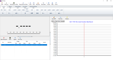
When starting the software looks this way on a Windows 10 computer. The software can basically remote control anything on the meter, except the range switch (Rel works differently: the reference value must be entered).

2s

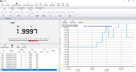
Connected to the meter and receiving data.

4s

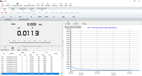
In AC ranges the frequency is shown together with the main value in the readout and in the table.

3x

The select button is controlled from this area.

7s

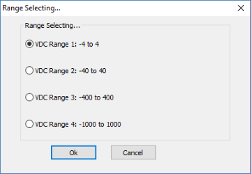
Using manual range select allows directly selecting the desired range.

6s

Downloading data from the meter is not very well designed, readings are fetched one at a time, this means the software can only download a few readings each second, i.e. it takes a long time downloading data.
Data will just be added to the current measurement set of data with the current time as timestamp.

log1

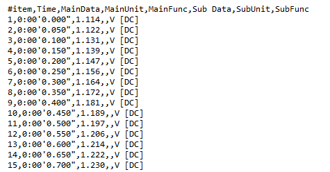
The software saves in a tab file format.

log2

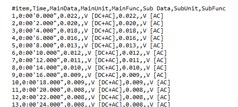
On lines where the secondary display showed a value this will be included in the line. There is no identification about what the second value is, except unit, this is problematic with min/max/avg/rel.


Tear down

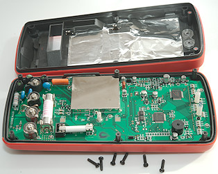
DSC_6983

I had to remove 6 screws to open the meter.

DSC_6984

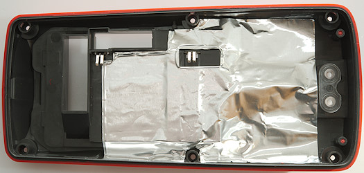
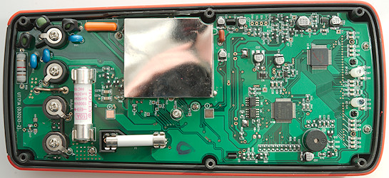
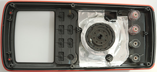
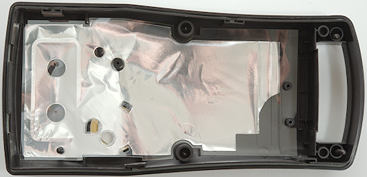
There is a lot of shielding in the meter, both metal foil in the back and a metal can on the circuit board.

DSC_6985

DSC_6986

Four screws for the input terminals and 5 more screws was holding the circuit board.

DSC_6987

There is also some shielding on the front. The current input terminals are in clear plastic.

DSC_6988

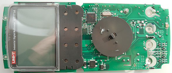
Display is mounted on the circuit board and the range switch also sticks to the circuit board.

DSC_6991

DSC_6993

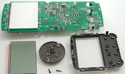
Two more screws and the display could be removed, the range switch could just be pulled off.

DSC_6994

It looks like we have the current shunts on this side, both for mA (R6A & R6B: 2×1ohm) and uA (R5: 50ohm). The protection for these shunts are some diodes (D1, D2, RV4) and the 0.8A fuse on the other side.
The analog frontend is also here (U2: HY3131 50000 count) and a reference (U7: MAX6190).
It looks like the top of the circuit board is antenna for the NCV input. The NCV led is also in that area (FG1). The backlight panel is soldered to the circuit board where it is marked BG+ and BG-.

DSC_7001

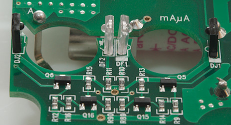
A closer look at the area around the A and mAuA input terminals. There is two leds (DF1, DF2) and two receivers (DJ1, DJ2) and then some circuit to amplify the signal. This is the probe detection for the terminals and the reason they are of clear plastic.

DSC_7002

DSC_6989

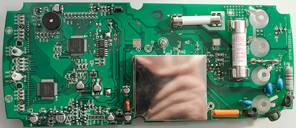
The can is blocking for some parts, what can that be?

DSC_6990

DSC_6992

At the V input there are two paths with PTC’s: First one uses two PTC’s (PTC1 & PTC3), the other path is a PTC (PTC2) and a resistor (R59: 1kOhm). Both path has a two MOV’s to COM input, one of them shared (RV3). The big orange part is a capacitor (10nF 1000V) used for AC ranges. There is also some transistor pairs for protection: mV, ohm, capacity (Q1 & Q2), ohm & capacity (Q3, Q4).
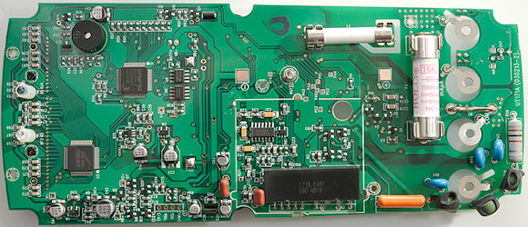
The can contains a large precision resistor and the true rms converter (U4: ES636).
Next up is two memory chips a EEPROM (U6: 24256E 32Kx8) and a flash (U5: M45PE40VP 512k*8), next to the microprocessor (U1: EFM32G232F128 ARM). This processor cannot directly drive a large LCD and need some help (U3: BU9799KV 50×4 LCD driver).
The two leds for the computer interface (DF3 & DJ4) is raised well above the circuit board.

DSC_6995

DSC_6996DSC_6998

DSC_6997


Conclusion

This meter looks well protected and may live up to its CAT rating.
It has good precision with all the common ranges, the computer connection works fine for logging, but off-line logging is not very useful. The high AC bandwidth and average function are nice details, but duty cycle do not handle high frequencies very well.
The mA and uA current ranges has lower burden voltage due to the lower shunt values, this is most obvious in the high uA range, but also helps slightly in the high mA range.
Generally a very nice and fast meter, but I am missing temperature measurement.


Notes

UNI-T do often make rebranded meters, i.e. it may exist with other names on it.

How do I review a DMM
More DMM reviews

My website with reviews of many chargers and batteries (More than 1000): https://lygte-info.dk/

Test/review of DMM Hioki DT4282

$
0
0
Forums: 

DMM Hioki DT4282

DSC_8199

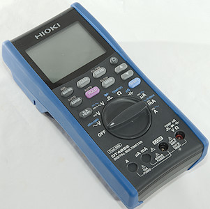
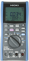
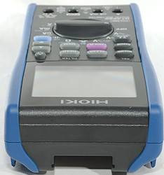
Hioki is a Japanese test equipment manufacturer, this multimeter is one of their top models.

DSC_8111DSC_8112DSC_8113DSC_8114

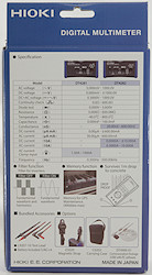
I got it in a cardboard box designed for the two top models, they can be compared on the back of the box. It also list what is in the box and some accessories.

DSC_8130

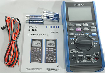
The box contained the meter, batteries, test probes and a manual in Japanese (A English manual can be downloaded). No thermocoupler or pouch.
The manual is very thorough with functions and specifications.

DSC_8131
DSC_8132
DSC_8133

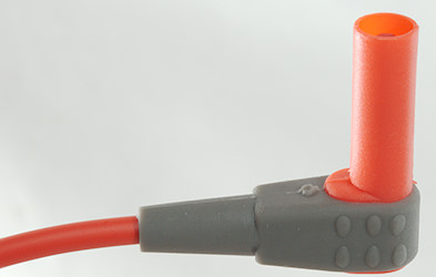
The probes has removable tip covers, the tip and tip cover has the usual CAT markings.

DSC_8134

The shrouded plug is full size.

DSC_8140DSC_8155

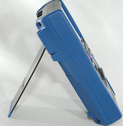
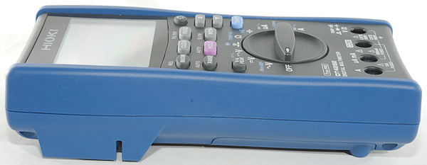
The range switch is fairly easy to turn and with this heavy meter it is stable both lying and standing. Due to the shutters plugs in the terminals can block the movement of the range switch.

DSC_8201

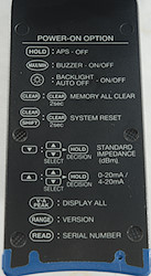
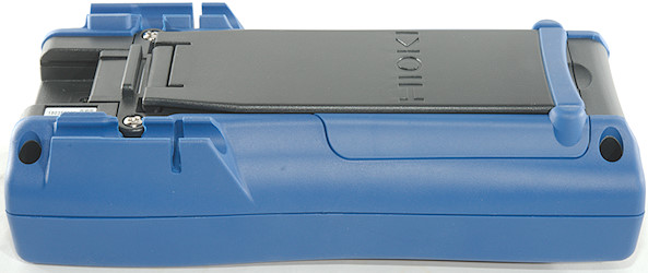
The meter has a couple of power on options (hold button down and turn on), some of them are saved (nice). To help remembering them the tilting bale has a list on the back.

DSC_8135

DSC_8136DSC_8137

DSC_8138

DSC_8139

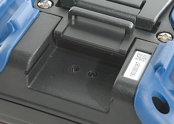
The computer interface is a small brick with a usb connector that is placed in this hole. The adapter is a bit expensive.
The serial number label can also be seen, this serial number was on the box and is coded into the meter and can be electronically read from the meter.

DSC_8202

DSC_8141


Display

DSC_8146

The above picture shows all the segments on the display, these are not shown on a normal power on, but using a power on option (VA PEAK), they can be shown.
The current clamp symbol is not used on this model.

DSC_8154

Typical display during usage, it will show the number and what measurement is selected.

DSC_8147

In AC ranges the frequency is shown on the secondary display.

DSC_8148

Some function will also use the secondary display.

DSC_8149

The memory uses its own counter on the display.
Secondary display functions (After / is small display):


  • AC volt: VAC/frequency, dBm/frequency, dBV/frequency
  • AC+DC volt: AC+DC/frequency, VDC/VAC
  • Continuity: ohm/threshold
  • Diode: volt/threshold
  • uA mA A: ADC, AAC/frequency
  • muA: ADC, AAC/frequency, %x-20mA
  • A: ADC, AAC/frequency
  • Peak: max/min


Functions

DSC_8152

Buttons:

  • Max/Min rel: Display maximum and minimum values, meter will always capture max/min values, this only shows the captured values. Hold down to store current value and show relative to this (Auto range is still active), hold down again to disable.
  • Clear: Clear max/min/peak values or a memory location.
  • Read/Filter: Recall memory locations, use up/down to select location, press read again to disable. Hold down to activate a LPF (Low pass filter) on VAC or AC+DC.
  • bglight: Turns on background light on/off.
  • Range/Auto: Press to select manual ranging, press again to change range, hold down for automatic ranging.
  • Hold (Pink): Freeze display reading, hold down for auto hold, i.e. meter will freeze any stable display reading.
  • Mem/Slow: Saves the displayed values to memory, hold down to enable a averaging filter on values.
  • updown: Arrow keys used to select memory number and to adjust some parameters.
  • VA Peak: Capture peak values in voltage and current modes, when this is active meter is in manual range.
  • Shift (Blue): Select the ranges printed with blue.

Rotary switch:

  • Off: Meter is turned off
  • VAC: Show AC voltage and frequency, use the blue button to select dBm or dBV.
  • VDC: Show DC voltage.
  • VAC+DC: Show AC+DC voltage and frequency or both AC and DC at the same time.
  • cont: Continuity and diode, on both the sensitivity can be adjusted with the arrows.
  • ohm: Resistance and temperature.
  • C: Capacity and conductance.
  • uA: Current DC and AC. In AC the blue button will show frequency and duty cycle.
  • mA: Current DC, AC and %x-20mA. In AC the blue button will show frequency and duty cycle.
  • A: Current DC and AC. In AC the blue button will show frequency and duty cycle.


Input

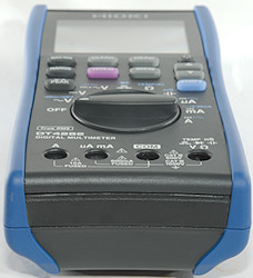
DSC_8153


  • 10A: High current.
  • mAuA: The lower current ranges, the selector switch will change between two different shunts.
  • CON: The common terminal for all ranges.
  • xxx: All other ranges.


Measurements

  • Volt and frequency

    • At 10mVrms VAC frequency input range is from 1Hz to 460kHz
    • At 100mVrms VAC frequency input range can be stretched to 500MHz that is maximum for meter.
    • At 420mVrms AC+DC frequency input range works from 1Hz to 500kHz
    • Max/min needs about 360ms to capture a voltage on DC.
    • Peak needs about 0.3ms to capture a voltage with repeating pulses on DC (It either need a slightly longer pulse or a few pulses to capture the full voltage).
    • Max/min is always active, using the max/min button will show the captured values. The button changes between max/min/actual.
    • 1 VAC is 5% down at 190kHz, AC+DC is 230kHz (RMS will not work at the frequency).
    • With filter (LPF) activated the range is locked to 600V & 1000V and I my generator do not have high enough output to test bandwidth
    • Frequency counter will automatic be shown in AC ranges.
    • Frequency input on AC do not require a zero crossing, on AC+DC the offset must be within about +/-5V
    • In dBm the following impedance can be used as reference: 4, 8, 16, 32, 50, 75, 93, 110, 125, 135, 150, 200, 250, 300, 500, 600, 800, 900, 1000, 1200
    • The AC+DC range has lower precision than the separate AC and DC ranges.
    • On this meter it is important to stay above 5% (or at least 2%) of AC ranges, they will not show correct at very low values and may even show 0.
    • Input impedance is 10..11Mohm on DC. VAC is a capacitor with 1Mohm after) and AC+DC is 1Mohm (This just about qualifies as a LowZ mode).
    • The meter has a special polarity function that can be enabled (Setting is stored) and will give alarm every time a voltage at -10 volt or lower is measured.
    • mV DC range is high impedance for DC up to around 1.5 volt where it drops to 10Mohm
    • Frequency input on AC volt is 1Mohm.
    • Over voltage protection is 1100VAC/DC

  • Current

    • Frequency counter will automatic be shown in AC ranges.
    • On over current the digits and red background light will flash and there is an audible alarm if over current is high range of uA, mA or A setting.
    • 600mA current is protected by a 0.63A/1000V 10.3×38mm fuse.
    • 10A current is protected by a 11A/1000V 10.3×38mm fuse.

  • Ohm, Continuity, diode and capacity

    • Ohm needs about 1s to measure 100ohm
    • Ohm is 0.48V open and 0.64mA shorted
    • Continuity is very fast (About 10ms).
    • In addition to the buzzer continuity also flashes the red background light.
    • Continuity has adjustable threshold: 20, 50, 100, 500ohm
    • Continuity beeps when resistance is below selected threshold (It is very precise) and continues to beep until resistance is considerable higher.
    • Continuity is 2.1V open and 0.64mA shorted
    • Diode range uses 4.3V, max. display is 3.600V at 0.19mA, max. current is 1.0mA shorted
    • Diode has adjustable threshold: 0.15, 0.5, 1.0, 1.5, 2.0, 2.5, 3.0V, buzzer and red light will be activated when voltage is below threshold.
    • 10uF takes about 2.8 seconds to measure.
    • 70000uF takes about 33 seconds to measure.
    • Over voltage protection is 1000VAC/DC

  • Miscellaneous

    • Current consumption of meter is 16 to 23mA depending on range (AC, continuity and capacity is 23mA), with backlight it is up to 42mA.
    • Meter works down to 3.7V where it shows “Batt lo” and turns off, battery symbol flashes at 4.4V.
    • Reading do not change with battery voltage.
    • Backlight is stable until the meter turns off due to low battery.
    • Meter has both a white backlight for lighting the display and a red backlight for notifying the user.
    • The meter will often show the correct value in first display update.
    • Viewing angle is good.
    • Display updates around 5 times/sec
    • Backlight will automatic turn off in about 40 seconds, this function can be disabled.
    • Meter will go to standby in about 15 minutes and turn off in 45 minutes, this can be disabled.
    • Standard probes fits perfectly.
    • Weight is 647g without accessories, but with batteries.
    • Size is 197 × 93 × 53mm.

  • Probes

    • Probe resistance 23mOhm for one.
    • Probe wire is fairly soft and 90cm long.


1uF

A look at the capacity measurement waveform.

DMMInputVoltageSweepmVDC

The input resistance in mVDC

DMMschema

Some AC ranges works down to 20Hz, but with lower precision.
The meter has a input impedance of 1Mohm in AC, this is nearly a permanent Low-Z (They are usual 0.3Mohm or lower).


Tear down


DSC_8203

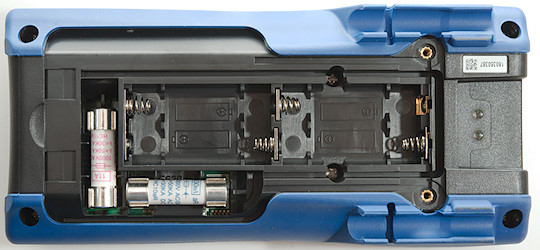
Six screws and the back could be removed, two of them are under the battery cover. It is necessary to remove one of the fuses to get the back cover up.

DSC_8204

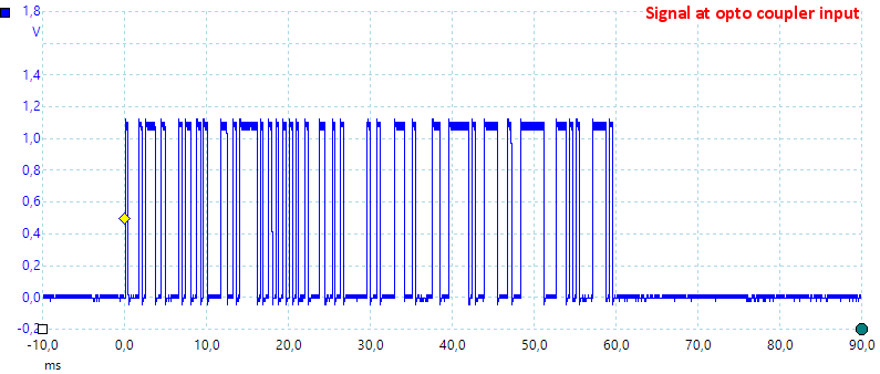
The battery box is part of the back cover with spring connections to the circuit board. There is also lenses for the opto communication.

DSC_8205

I did not really get to see much, there is a secondary cover.

DSC_8206

DSC_8207

I only had to remove one screw to remove it (This screw holds all the internal covers), but there are more internal covers.
The internal cover is conductive plastic, pressing two probes into it gives about 600-1000ohm at any distance.

DSC_8208

DSC_8209

Removing the screws on the terminals allowed my to take the circuit board out.

DSC_8210

DSC_8211

The other side of the circuit board also has internal covers.

DSC_8212

DSC_8213

But they are loose now.

DSC_8214

DSC_8215

The display was mounted with two screws and the backlight was soldered to the circuit board.

DSC_8226

The backside of the backlight is shielded and it has 3 connections (red + white led and common).

DSC_8230

The circuit board and all the internal covers are one unit and can be removed when unscrewed from the terminals (This image is from when I put it together again).

DSC_8217

The current input do not use the common 10A wire shunt, but a regular smd resistor (R26: 0.01ohm), the mA (R27: 1ohm) and uA (R28: 100ohm) is just next to it. The protection diodes (D1..D9) is mounted next to the mA fuse. The voltage input is also a bit uncommon with only a single PTC with series resistor (R25: 470ohm) and a spark gab (Most meters has dual paths with PTC’s). This meter do not use protection on the 10Mohm (R1..R4: 4×2.55Mohm) or 1Mohm (R8..R11: 4×250kOhm) paths, but has some fairly large resistors for it.
An interesting detail is all the gold traces, they are guard traces, i.e. placed around sensitive areas and kept at the same voltage usual with an OpAmp, this means very low leakage current from the sensitive area.
Most of the range switching must be electronic, the meter is packed with analog switches: IC1: AD8539, IC3: 4051, IC5: ADG609, IC6: 4053, IC7: ADG409, IC21: AD8539, IC24: ADG711, IC26: 4053 and more. I did also see some OpAmps IC1: AD8539, IC12: AD8539, IC20: AD8539
The big chip (IC31) is probably a UPD78F1518A 16 bit microcontroller and next to it is a 24bit ADC (IC211: ADS1247). The RMS converter is from LT (IC13: LTAFG/LTC1968)
The above list of chips is not complete, it is fairly complicated to build a high-end meter without using a multimeter chipset.

DSC_8218

DSC_8219DSC_8221

DSC_8220

DSC_8216

DSC_8222

DSC_8225DSC_8227

DSC_8228DSC_8229

The above 4 images are for people that want more detailed pictures of the circuit board (Most chip numbers can be seen on them).


Conclusion

This meter is a high-end meter with many functions and very good precision, I also expect the CAT rating is correct. The functions generally works very fine and fast, but I found a few limitations: LPF can only be used on 600V & 1000V range, I am missing duty cycle and average (In some cases the filter function can substitute) and I do not know how useful 400 memory locations are.
The user interface is slightly different to most other multimeters with min/max always active and a CLEAR to reset both min/max and peak without disabling them.

I like the meter, user interface and how fast it is.


Notes

How do I review a DMM
More DMM reviews

My website with reviews of many chargers and batteries (More than 1000): https://lygte-info.dk/

Test/review of DMM BSide ACM91 (Clamp)

$
0
0
Forums: 

DMM BSide ACM91

DSC_7877

A clamp meter from BSide with a DC sensitivity of 1mA, it do also have a lot of other ranges including temperature.

DSC_7831

I got the meter in a brown cardboard box with a label specifying the contents.

DSC_7862

DSC_7863

The pouch.

DSC_7864

It included the DMM, a pair of probes, a thermocoupler and a manual.

DSC_7871
DSC_7872
DSC_7873

The probes is branded BSide and has removable tip covers. With the cover on they are CAT III 1000V rated

DSC_7874

The shrouded plug is the slightly short variety.

DSC_7875
DSC_7876

The thermocoupler is the cheap type with banana plugs.

DSC_7924

DSC_7869

A probe holder for one probe, this means it only requires one hand to hold the meter and stick the probe somewhere, the other hand can be used for the black probe.

DSC_7878

DSC_7879

DSC_7880DSC_7881

DSC_7882


DSC_7883


Display

DSC_7923

The above picture shows all the segments on the display, not all are used by this meter.
The small display is used for frequency in AC modes and Fahrenheit temperature when measuring temperature.

DSC_7893

Typical display during usage, it will show the number and what measurement is selected.

DSC_7925

In AC modes the frequency is included on the secondary display.

DSC_7927

Non contact voltage or electric field will show —— when no field and NCV with red background light and buzzer sounding when a field is detected.

DSC_7945

Live detection will show —— when no mains is detected and LIVE with red background light and buzzer sounding when a something is detected.


Functions

DSC_7897

Buttons:


  • on: Press to turn meter on or off.
  • SEL/Zero: Select AC and ohm/continuity/capacity. Hold down to zero clamp in DC mode.
  • H/light: Freezes the display, hold down for backlight.
  • V~Alert: Hold down for NCV function.

Rotary switch:

  • Live: Detect mains voltage with a single probe.
  • A: Clamp measurement of DC and AC current.
  • V: Measurement of voltage om input terminals.
  • LoZV: Measurement of voltage om input terminals, with low impedance. AC/DC is automatic.
  • ohm: Resistance, continuity and capacity.
  • Temp: Temperature measurement with thermocoupler
  • uA: Low DC Current measurement with probes.


Input

DSC_7896

Clamp, used for DC and AC current measurement, except uA

DSC_7898

These terminals are used for Voltage, ohm, continuity, capacity, temperature and uA.

  • CON: The common terminal
  • INPUT: The positive terminal.


Measurements

  • Volt and frequency

    • At 100mVrms input frequency range is from 10Hz to 3kHz
    • At 2Vrms input frequency range is from 10Hz to 3kHz
    • 1 VAC is 5% down at 2.1kHz (RMS will not work at the frequency).
    • Frequency input requires a zero crossing.
    • Frequency counter is dual display in AC ranges.
    • LowZ has automatic DC/AC selection.
    • LowZ starts in DC and will switch to AC when voltage is above 1VAC without any DC.
    • Input impedance is 10..11Mohm on DC and AC
    • LowZ is 1Mohm input impedance.

  • Current

    • Frequency counter is on secondary display in AC ranges.
    • uA uses the probe inputs.
    • Initial DC offset on clamp is about 260mA, doing a demagnetizing I got it down to 70mA
    • uA current is protected by the PTC’s
    • Clamp can handle about ø18mm

  • Ohm, Continuity, diode and capacity

    • Ohm needs about 2.8s to measure 100ohm
    • Ohm is 0.51V open and 0.37mA shorted
    • Continuity is fast (About 30ms, but most of the time 3mS).
    • Continuity beeps when resistance is below 30ohm.
    • Continuity is 1V open and 0.37mA shorted
    • 10uF takes about 2.2 seconds to measure.
    • 6000uF takes about 8 seconds to measure.
    • Overload protection 250VDC/VAC

  • Miscellaneous

    • Current consumption of meter is 19mA and 24mA when using clamp (26mA with backlight in clamp mode).
    • Meter works down to 2.2V where it turns off, battery symbol shows at 2.4V.
    • Reading do not change with battery voltage.
    • Backlight only works down to about 2.6V where it is fairly dim.
    • The meter usual need a couple of display update to reach the final value.
    • Viewing angle is good.
    • Display updates around 3 times/sec
    • Backlight will automatic turn off in about 60 seconds.
    • Will automatic turn power off in about 30 minutes (Manual says 20 minutes).
    • Standard probes cannot be pushed fully down.
    • Weight is 161g without accessories, but with batteries.
    • Size is 180 × 70 × 32mm, the large with is due to probe holder on one side and clamp button on the other side.

  • Probes

    • Probe resistance 54mOhm for one.
    • Probe wire is soft and 78cm long.


10uF

A look at the capacity measurement waveform, this time with a 10uF capacitor.

DMMInputVoltageSweepVAC

Frequency input resistance is AC input have about 10Mohm (LowZ is 1MOhm).

DMMschema

The clamp will change offset for a long time (More than 1 minute) on the A range, this basically makes it impossible to measure below 10mA
Auto range in capacity has a problem, it may lock up between 600uA and 1000uF
Minimum capacity value is 2uF, any value below that will show 0.
The software in the meter is not completely stable, it crashed a couple of times during my test
The power switch is not 100% reliable, sometimes it turns on/off or off/on when pressed once.


Tear down

DSC_7950

Four screws and the back could be removed.

DSC_7949

There was a small detail about locating the screws first, one was behind the serial number label another behind the belt clip.

DSC_7951

DSC_7952

Circuit board is nicely adapted for the enclosure. There is a flat flex for the current sensing and a red wire for the NCV going into the clamp.

DSC_7954

DSC_7955

The circuit board had 6 screws, that was 3 screws for the display and 3 to hold the circuit board.

DSC_7962

The clamp was mounted with two screws.

DSC_7963DSC_7964

DSC_7965

DSC_7957

At the clamp there are some chips for handling the signal (U3, U5: ETM1792A: Probably Dual OpAmp, U4: Marked 3157F: Maybe Voltage regulator). The chip (U9: Marked 7W74 7F, maybe D-FlipFlop) may be to handle power. Near the battery connection is also another chip (U7: R11, Maybe LM385 reference). The big chip (U8: Holtek HT1621B, LCD memory) is for interfacing the LCD display, the DMM chip (U11) must be lacking that function. There is a EEPROM for parameters to the DMM chip (U2: 24C02A) and probably some calibration, there is also a couple of trimpots for the clamp.
For the input there is a couple of paths: two PTC’s in series for ohm and uA, a 900kOhm path for temperature and ohm feedback and two resistor for voltage input (R7A & R7B: 2×5Mohm). The ohm and uA input uses a transistor pair (Q4 & Q5) to clamp the voltage.
The LowZ is made with 3 SMD resistors (R23, R24, R25: 3×300k), they are after the PTC’s.

DSC_7958

DSC_7959DSC_7961

DSC_7960

DSC_7956

On this side is only the backlight led and the pads for switches and LCD

DSC_7968


Conclusion

Specifications sound good and the meter has many functions, but it is not perfect, there are a couple of issues. It is lacking diode testing, capacity test is not very good and frequency range is fairly limited. Compare to other clamp meters it add temperature, a uA mode and LowZ. The NCV and Live mode is also a nice touch.


Notes

How do I review a DMM
More DMM reviews

My website with reviews of many chargers and batteries (More than 1000): https://lygte-info.dk/

Test/review of DMM Sanwa PM3

$
0
0
Forums: 

DMM Sanwa PM3

DSC_6749

This is a small pocket DMM with voltage, ohms and capacity, but without current.

DSC_6711DSC_6712

The meter was in a clamshell pack. On the back is a some explanation about using the meter.

DSC_6743

In the pack was the meter and a manual in English.

DSC_6750

The probes and wires need some pressure to close the cover.

DSC_6752

The probes are small and without any markings.

DSC_6764

The probes are directly connected to the meter, no plugs and sockets.

DSC_6761

The range switch is easy to turn, there is not many selections, Sanwa has decided to use a buttons for many measurements

DSC_6751DSC_6754

DSC_6755
DSC_6756
DSC_6757
DSC_6758


Display

DSC_6760

The above picture shows all the segments on the display.

DSC_6762

Typical display during usage, it will show the selected range and value.


Functions

DSC_6763

Buttons:


  • Select: Select between ohm, diode, continuity and capacitance
  • Relative: Store current display value and show all new values relative to this value.
  • Hold: Will freeze the display reading, until pressed again.
  • Hz/duty: Will select between voltage, frequency and duty cycle in both DC and AC.

Selection of Relative and Hz/duty will disable auto ranging and it stays disabled
The Select and Hz could have been combined, they are not used in the same ranges.

Rotary switch:

  • Off: Meter is turned off
  • VDC: DC voltage and frequency/duty cycle.
  • VAC: AC voltage and frequency/duty cycle.
  • ohm: Ohm, diode continuity and capacitance.


Input

DSC_6753

This meter only have a red and black probe comming out, no other connections.


Measurements

  • Volt and frequency

    • At 1V rms input on DCV/ACV the frequency counter range is from 0.5Hz to 8kHz
    • At 2V rms input on DCV/ACV the frequency counter range is up to 15kHz
    • At 5V rms input on DCV/ACV the frequency counter range is up to 21kHz
    • Duty cycle works from 5% to 96% at 1kHz with 4Vpp, precision is within 0.8 (Mostly 0.3)
    • Both DC and AC frequency counter inputs need a zero crossing.
    • 1V AC readings is 5% down at 2kHz
    • V input impedance is 10-11Mohm,
    • mV input impedance is high below 1.5V and drops to 10MOhm above.
    • Frequency on DC is high impedance below 1.5V and drops to 10Mohm above.
    • Input protection is 500V AC/DC.

  • Current

    • There is no current ranges

  • Ohm, continuity, diode and capacity

    • Ohm needs about 3.5s to measure 100ohm
    • Ohm is 0.43V open and 0.16mA shorted
    • Continuity is very fast (
    • Continuity beeps when resistance is below 20ohm and makes noises up to about 50ohm
    • Continuity is 0.44V open and 0.16mA shorted
    • Diode range uses 1.5V, max. display is 0.999V at 0.1mA (Real voltage is 1.1V), max. current is 0.44mA shorted
    • 200uF takes about 43 seconds to measure.
    • Rated overload protection is 500 VDC/VAC

  • Miscellaneous

    • Current consumption of meter is 1.6mA except in AC where it is 2.2mA
    • Meter starts to fade at 2V and fails below 1.6V, battery symbol shows at 2.3V.
    • Readings will drift about 8 count from when battery symbols shows to the meter fails.
    • Viewing angle is good
    • Display updates around 3 times/sec
    • Will automatic turn power off after about 15 minutes
    • The meter often need many display update to reach the final value.
    • Weight is 91g without accessories, but with sleeve and batteries.
    • Size is 108 × 5 × 12mm (probes not included) and 120 × 79 × 16 in sleeve.

  • Probes

    • Probe wire is a bit thin, the are 41cm long.


1uF

Capacity measurement waveform.

DMMInputVoltageSweepHzVDC

Frequency input resistance in voltage DC position, mVDC is similar.

DMMInputVoltageSweepHzVAC

Frequency input resistance in voltage AC position.

DMMschema

The meter cannot measure low AC volt when there is a large DC voltage.


Tear down

DSC_6757

I had to remove one screws, to open it, this is also required when replacing battery.

DSC_6858

DSC_6859

To get the circuit board out I had to remove 6 screws and a locking ring.

DSC_6860

DSC_6861

The multimeter chip (FS9711_LP1 (See FS9721_LP1 datasheet)) is the most obvious feature on the circuit board. The circuit around D1 and R2 is rectifier for AC voltage. The range selection resistors are near the range switch (Most of R21..R30) and is selected by the chip. The input resistor is 5 resistors (R15, R17 & R31, R32, R33: 5×2Mohm) placed at two locations. The input is also going through a PTC (R14) and protection transistor (Q1), this is for ohm ranges, in ohm there is also a need for another input path (R12 1Mohm).
The buzzer has a transistor and inductor to get as much sound as possible (It is not very loud).

DSC_6862

DSC_6864

DSC_6863DSC_6865

DSC_6867

On this side is only the buzzer and access to the battery, there is cut-outs for the crystal and the PTC.

DSC_6866


Conclusion

The meter says CAT II 500V, but this rating is either 300V or 600V, there is no 500V. The safety looks acceptable for 300V.
The meter does not have current ranges, this improves the safety, but limits the abilities of the meter. The meter has some limits in its range, but for a pocket meter is it fairly decent.


Notes

How do I review a DMM
More DMM reviews

My website with reviews of many chargers and batteries (More than 1000): https://lygte-info.dk/


Test/review of DMM UNI-T UT195DS

$
0
0
Forums: 

DMM UNI-T UT195DS

DSC_7902

This is a industrial grade DMM designed for electricians. This is the the most advanced of the meters in the 195 series.

DSC_7899

I got it without the box, but in the pouch.

DSC_7900

With all parts inside.

DSC_7901

That was the meter, the probes and a Chinese manual (I could download an English version).

DSC_7903
DSC_7904

Probes are branded UNI-T and rated for 20A, they have very low resistance this means the 20A rating is probably good enough.

DSC_7905

With a tip cover they are CAT IV 600V or CAT III 1000V, without CAT II 1000V (This is fairly standard for probes).

DSC_7906

The plugs are fully shrouded, but the shroud is a bit short

DSC_7910DSC_7922

The meter is a bit heavy and the range switch easy to turn, this means it can easily be used with one hand, either lying flat or standing.

DSC_7907

All the red plastic is slightly rubberized in feel including the range switch.
The red plastic works as bumpers from any direction.

DSC_7908DSC_7909

DSC_7913

The battery/fuse compartment is sealed and due to that the lid uses 5 screws, that usual stays in the lid (i.e. no lost screws).

DSC_7912

The flashlight led and a hanger.


Display

DSC_7916

All the segments are shown during power on. A few symbols are not used by this meter.

DSC_7917

Typical display during usage, it will show the number and selected measurement and sometimes the secondary display.
Secondary display functions:


  • In AC+DC secondary display will change between AC and DC voltage automatic.
  • In AC it will show frequency.
  • When min/max is active it will show min/max, main display shows actual value.
  • When Peak is active it will show peak min/max, main display shows actual value.
  • In frequency it will show duty cycle.


Functions

DSC_7918

Buttons:

  • Range: Select manual range and change range, hold down to reactivate automatic ranging
  • Max/min: Capture maximum and minimum values, secondary display will show value. Hold down to disable.
  • Rel: Shows values relative to current value, will also select manual range. Press again to disable.
  • Peak: Capture peak values, this can only be used in AC modes, secondary display will show value. Hold down to disable.
  • Hold (Yellow): Will freeze the display reading, until pressed again.
  • backlight: Turn automatic backlight off until next power cycle.
  • flashlight: Turn flashlight on or off.
  • Select (Blue): Select DC/AC in voltage and current modes, continuity and diode in ohm mode.

Rotary switch:

  • LoZ: Low input impedance (300kOhm), range is always 600VAC.
  • Off: Meter is turned off
  • VAC: AC voltage and peak detection, frequency is on secondary display when measuring AC.
  • VDC: DC voltage and AC+DC voltage
  • mV: AC or DC millivolt
  • ohm: Ohm, continuity and diode
  • capacitance: Capacitance.
  • Hz: Logical frequency input and duty cycle.
  • uA: Microampere DC or AC, frequency is on secondary display when measuring AC.
  • mA: Milliampere DC or AC, frequency is on secondary display when measuring AC.
  • A: Ampere DC or AC, frequency is on secondary display when measuring AC.


Input

DSC_7919


  • uAmA: Micro and milliampere input.
  • 20ADC: 20A DC current input.
  • COM: The common terminal for all ranges.
  • xxx: All other ranges.


Measurements

  • Volt and frequency

    • Millivolt range starts in AC
    • 1V AC readings is 5% down at 20kHz (Both AC and AC+DC), rms will not work at that frequency
    • 1V AC readings in LPF mode is 5% down at 600Hz, rms will not work at that frequency
    • Frequency input do not require a zero crossing.
    • At 1Vrms frequency input range is from 1.1Hz to 22MHz
    • At 2Vrms frequency input range is stretched to 40MHz
    • Duty cycle works from 1% to 90% at 100kHz with 2Vpp, precision is within 2.0.
    • Duty cycle works from 1% to 99% at 100kHz with 4Vpp, precision is within 0.3.
    • Default range for LPF mode is 1000VAC, but it can be changed with the RANGE switch (Mode do not support auto ranging).
    • Max/min needs about 150ms to capture a voltage, auto range is disabled when using this function.
    • Peak only work in AC and needs about 0.5ms to capture a voltage, auto range is disabled when using this function.
    • Input impedance is 10-10.1Mohm on DC and AC
    • mVDC is high impedance up to about 3V where it drops to about 100kOhm, above 12V it will drop to 3kOhm
    • mVAC is the same, but capped by a 10MOhm resistor.
    • LowZ is constant 300kOhm input impedance and is locked in 600VAC range.
    • Input protection is 1000VDC/750VAC

  • Current

    • 20A range has audible alarm above 20A
    • 20A range is fused with a 11A/1000V 10×38mm fuse
    • mAuA range is fused with a 0.6A/1000V 6×32mm fuse
    • Current ranges starts in DC

  • Ohm, continuity, diode and capacity

    • Ohm needs about 1s to measure 100ohm
    • Ohm voltage is -1.1V open and -0.24mA shorted.
    • Continuity is very fast (About 3ms).
    • Continuity beeps when resistance is below 30ohm.
    • Continuity is -3.3V open and -0.93mA shorted
    • Diode range uses 3.1V, max. display is 2.800V at 0.11mA, max. current is 1.1mA shorted
    • 10uF takes about 1 seconds to measure.
    • 11000uF takes about 10 seconds to measure.
    • Overload protection is 1000V

  • Miscellaneous

    • Current consumption of meter is 5mA to 8.5mA depending on range (21mA with flashlight, 12mA with background light, max. 26mA).
    • Meter turns off at 5V, battery symbol show at 7.2V.
    • Readings will be correct until the meter turns off
    • Backlight fades with dropping voltage and is mostly gone at 5.5V
    • Flashlight fades slightly with dropping voltage, but is still bright when the meter turns off at 5V
    • Viewing angle is good
    • Display updates around 5 times/sec
    • Bargraph is about 20 updates/sec
    • Backlight will automatic turn on when in dark surroundings
    • Flashlight will not turn off automatic, but turns off with the auto power off.
    • Will automatic turn power off in about 15 minutes.
    • Standard probes can nearly be fully seated in the meter.
    • The meter need one or two display update to before it display the final value.
    • Weight is 41g without accessories, but with battery.
    • Size is 195 × 96 × 61mm

  • Probes

    • Probe resistance 14mOhm for one, that is very low.
    • Probe wire are 88cm long and feels a bit stiff, probably due to the thickness.


1uF

A look at the capacity measuring waveform with a 1uF capacitor.

DMMInputVoltageSweepHz

Frequency input is 3Mohm to 10Mohm up to 12V where it drops to 3kOhm

DMMInputVoltageSweepmVDC

mVDC is high impedance up to about 3V.

DMMschema


Tear down

DSC_7969

I had to remove 6 screws to open the meter. This meter uses metal inserts for the screws and they stay in the bottom (very nice).

DSC_7970

DSC_7971DSC_7972

The flashlight, it uses two metal strips for contact to the circuit board.

DSC_7973

The main DMM chips are hidden under a metal can.

DSC_7974

DSC_7975


Four small screws and for larger screws at the input terminals, then I could remove the circuit board.

DSC_7976

To see the buttons I needed to remove 3 more screws.

DSC_7978

A flex circuit board is used for the buttons.

DSC_7979

DSC_7977

DSC_7980

DSC_7981

DSC_7982

DSC_7983

I am not that happy about the can, I need to remove the display and backlight, before I can remove it.

DSC_7984

Two screws to remove the display, solder two wires to remove the backlight and four more soldering to get the can away.

DSC_7986

The 20A shunt (R23A & R23B) is really large in this meter, that probably means it can handle 10A for a very long time without getting too warm. The smaller current ranges are handle by two smaller resistors (R24: 1ohm & R25: 99ohm), with a diode bridge (D9..D13) and transient diode (TVS1) for protection. The voltage input has two paths, both protected with dual PTC’s (PTC1, PTC2, PTC1A1, PTC2A1) and MOV’s (SG1, SG2, SG3). The voltage path is 4 resistors (R1..R4: 4×2.5Mohm) with the optional LowZ resistor (R21: 300kohm).
There is also a lot of transistor pairs for protection mv (Q3 & Q4), ohm & capacity (Q7 & Q8 and Q5 & Q6), frequency (Q1 & Q2). There is also a pair switched into the voltage input when in the uA range (Q9 & Q10), I wonder why.
All the diodes near the battery terminals (DD1..DD6 & D4..D8) I supposed are used for coding the range switch correctly for the multimeter IC.
The two chips (U7 & U8: marked PAO) are probably voltage regulators. The larger chip (U4: ES5) is a RMS converter. Below the can we have the multimeter chip (ES222), a microprocessor (U2: EFM32ZG222F32, 32kB flash, 4kB ram), a EEPROM (U5: 24256E 32Kx8) and a LCD driver (U3: HY2613B 4×36).

DSC_7987

DSC_7988DSC_7990

DSC_7989

DSC_7985

The only part on this side is the LDR for automatic backlight and then there is the pads for the range switch and LCD display.

DSC_7991


Conclusion

This meter has a lot of protection, i.e. the CAT rating is probably correct.
This meter has a good selection of ranges and functions, including peak, LowZ and flashlight. With the fairly high AC bandwidth the LPF function can also be useful. The automatic backlight looks like a useful feature. I am missing temperature and average.

This meter looks to be a rather robust meter


Notes

UNI-T do often make rebranded meters, i.e. it may exist with other names on it.

How do I review a DMM
More DMM reviews

My website with reviews of many chargers and batteries (More than 1000): https://lygte-info.dk/

Test/review of DMM Fluke 289 (Used)

$
0
0
Forums: 

DMM Fluke 289 (Used)

DSC_8380

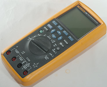
This has been the top multimeter from Fluke for many years. Here I am looking at my old (2009) copy of the meter. This means I cannot say anything about the box or accessories it was delivered with.

DSC_8389DSC_8442

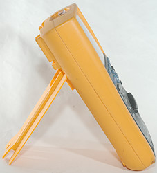
The range switch is fairly easy to turn and with this heavy meter it is stable both lying and standing.

DSC_8381

DSC_8382DSC_8383

DSC_8388
DSC_8384

DSC_8385

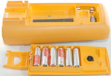
The meter needs 6 AA batteries.

DSC_8386
DSC_8387

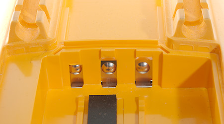
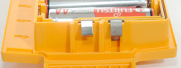
There is 3 connection on the meter, but only two on the battery tray.


Display

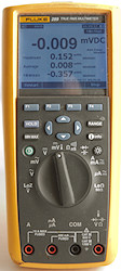
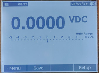
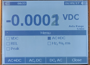
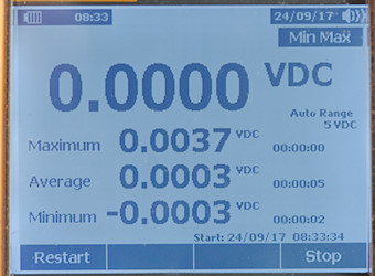
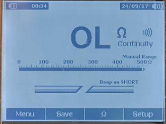
The meter uses a graphical display, this means fairly low contrast, but it can show many different layouts. To get the pictures here I used the background light on the display.

DSC_8432

The meter has a build in manual.

DSC_8431

A fairly simple display for showing volt DC. The soft keys shows the usual functions:
Menu: Options for the current selected range.
Save: Save one or more values or look at the saved values.
Empty: Use for some shortcuts and range specific functions.
Setup: General meter setup and calibration.

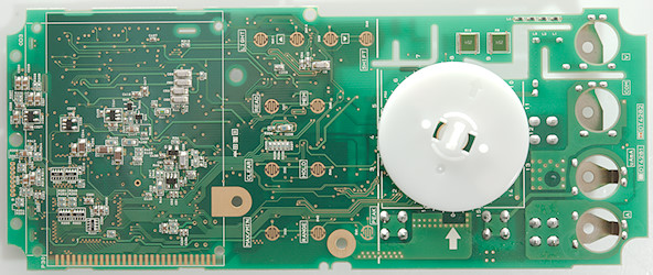
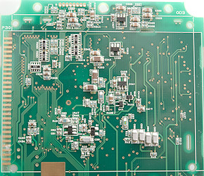
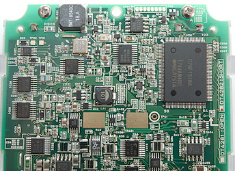
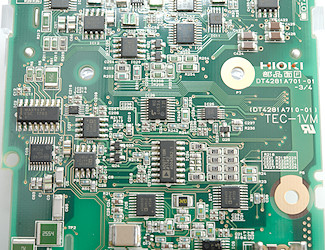
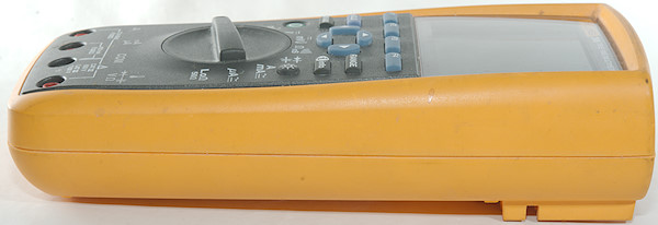
DSC_8435

Here is the “Menu” for DC, the arrow keys are used to move the black square around and each location has one or more functions. For this menu there are a total of 10 functions (VDC, Rel, Rel %, Peak, AC+DC, AC,DC, DC,AC, Hz, %, ms).

DSC_8436

The min/max (and peak) display shows all the values at once, including time stamps for when the event occured.

DSC_8437

Continuity shows resistance, bargraph and a graphic on open/short. There is a shortcut key to change between ohm and continuity, to avoid using the menu button (For nS the menu must be used.

DSC_8439

When current ranges is selected a warning will be shown until leads are plugged into the current terminals.
If leads are in the current terminals in other ranges both the warning and the buzzer will be used to warn.

DSC_8440

The meter saves data in record sets with data time and samples. Events is used to capture changing values that happens between sample intervals and will add extra sample points. Default setting is that a 4% change will add a event, but it can be adjusted.

DSC_8441

The meter can also show captured data in graphical form and it is possible to zoom on the data.

DSC_8433

The setup function makes it possible to see some information about the meter (Like calibration data and software versions) and adjust a couple of preferences.

DSC_8434

Here is most of the preferences.
Secondary display functions (After / is secondary values):


  • REL: relative/reference/absolute
  • min/max: value/min/average/max each with time of event.
  • Peak: value/min/average/max each with time of event.
  • VAC-LPF: VAC, frequency/VAC
  • Frequency: frequency/VAC, percent/frequency, puls_time/frequency
  • dB: dBm/VAC, dBm/frequency, dBV/VAC, dBV/frequency
  • VDC: AC+DC, VAC/VDC, VDC/VAC
  • VAC: Crest_factor/VAC
  • IDC: AC+DC, IAC/IDC, IDC/IAC
  • IAC: Crest_factor/IAC


Functions

DSC_8417

Buttons:

  • F1: Usual “Menu”, but when special functions are active it can be other function (Like “Restart” in min/max/peak)
  • F2: Usual “Save”
  • F3: Usual empty, but used for shortcuts and other stuff when required.
  • F4: Usual “Setup”, but also “Stop” and “Close” for min/max/peak/record.
  • Hold: Freeze the display, when this is activate F1 can be used for auto hold. Press again to disable.
  • arrows: The arrows are used for menu and parameter selection (Up/Down is also contrast adjustment).
  • Range: Change to manual range and change range, hold down to disable.
  • Min Max: Activate min/max function, press again to stop and press once more to return to normal mode (The last two can also be done with the F-keys).
  • Info: Build in manual.
  • power: Power button, a press will turn on the meter. This button will be illuminated when meter turns on, it turns off when the meter is on and flash when logging in low power mode.
  • light: Background light, the meter has two brightness settings.

Rotary switch:

  • LoZ VAC: LowZ mode, it will show both DC and AC voltage
  • VAC: Show AC voltage, frequency, dBm, dBV, Crest factor
  • mVAC: Show AC voltage, frequency, dBm, dBV, Crest factor
  • VDC: Show DC voltage, frequency, AC+DC, AC and DC.
  • mVDC: Show DC voltage, frequency, AC+DC, AC and DC. Temperature input is also selected here.
  • ohm: Resistance, continuity and conductance (nS).
  • C: Capacity and diode.
  • A mA: Current DC, AC, frequency, crest factor
  • uA: Current DC, AC, frequency, crest factor
  • LoOhm: The lowest ohm range, uses a higher current than other ranges and has a 1mOhm resolution.


Input

DSC_8418


  • A: High current, it is possible to use 20A for 30 seconds
  • mAuA: The lower current ranges, the selector switch will change between two different shunts.
  • CON: The common terminal for all ranges.
  • xxx: All other ranges.


Measurements

  • Volt and frequency

    • At 10mVrms in mVAC frequency input range is from 0.4Hz to 500kHz
    • At 100mVrms in mVDC and mVAC frequency input range is from 0.4Hz to 1MHz (The meter shows OL above 1MHz)
    • At 2Vrms in DC frequency input range is from 0.4Hz to 15kHz
    • At 2Vrms in AC frequency input range is from 0.4Hz to 500kHz
    • Duty cycle works from 2% to 95% at 100kHz with 1Vpp in mVDC, precision is within 2.0
    • Duty cycle works from 1% to 99% at 10kHz with 1Vpp in mVDC, precision is within 0.14
    • Max/min on VDC needs about 200ms to capture a voltage on DC, it will need multiple pulses to get the full value.
    • Peak on VDC needs less than 0.1ms to capture a voltage with repeating pulses on DC (It either need a slightly longer pulse or a few pulses to capture the full voltage).
    • Peak on AC is just as fast, but due to the capacitor in series with the input it will not show DC values.
    • Min/max on AC is slightly slower, but due to the capacitor in series with the input it will not show DC values.
    • Min/max/peak do not disable auto range.
    • 1 VAC on AC input is 5% down at 125kHz, with LPF (Low pass filter) it is 5% down at 410Hz (RMS will not work at the frequency).
    • 1 VAC on DC input (i.e. AC or AC+DC) is 5% down at 45kHz (RMS will not work at the frequency).
    • Frequency counter on DC requires a zero crossing.
    • Frequency counter on AC is capacitor coupled and do not require a zero crossing.
    • LowZ is a fixed 1000V range that shows both VAC and VDC (Not AC+DC)
    • In dBm the impedance can be adjusted in 1ohm step from 0001 to 1999ohm (It is done in the configuration menu)
    • Input impedance is 10..11Mohm on DC. AC and mVAC is a capacitor (Impedance is around 10Mohm).
    • mV DC range is 10Mohm impedance up to around 2.6 volt where it slowly drops to 2kOhm
    • Over voltage protection is 1000V

  • Current

    • On over current in mA (440mA) or A (10A) the display will flash
    • When selecting current ranges with probes in wrong terminal display will show a warning
    • When selecting non-current ranges with probes in current terminal there will be an audible alarm and the display will show a warning.
    • 400mA current is protected by a 0.44A/1000V 10.3×38mm fuse.
    • 10A current is protected by a 11A/1000V 10.3×38mm fuse.

  • Ohm, Continuity, diode and capacity

    • Ohm needs about 2.5s to measure 100ohm
    • LowOhm needs about 2s to measure 10ohm
    • LowOhm is 2.6V open and 8.8mA shorted
    • Ohm is 3.9V open and 1mA shorted
    • nS is 3.9V open and 0.35uA shorted
    • Continuity is very very fast (Below 1ms).
    • Continuity start beeping when resistance is below 50ohm and stops beeping when resistance is above 94ohm
    • Continuity is 5.4V open and 1mA shorted
    • Diode range uses 5V, max. display is 3.1000V at 0.8mA, max. current is 1.0mA shorted.
    • 10uF takes less than 0.5 second to measure.
    • 70000uF takes between 4 and 10 seconds to measure.
    • Over voltage protection is 1000V

  • Miscellaneous

    • Current consumption of meter is about 22mA, 36mA with low backlight and 58mA with high backlight
    • Meter works down to 5.3V where it shows “Batteries critical low, replace now” and turns off, battery gauge shows empty at 6.2V.
    • Reading do not change with battery voltage.
    • Power on time is about 8 second from on button lights up until first reading is on the display.
    • Backlight is stable until the battery gauge shows empty, then it turns off and cannot be turned on again.
    • The meter needs a few display update before it shows correct value.
    • Viewing angle is good, but contrast is fairly low.
    • Display updates around 4 times/sec
    • Bargraph updates 30 times/second
    • Bargraph will be 0..max or min..0..max depending on range.
    • Backlight automatic turnoff is adjustable from: off/5/10/15/20/25/30 minutes.
    • Auto turn off is adjustable from off/15/25/35/45/60 minutes
    • Standard probes fits perfectly.
    • Weight is 805g without accessories, but with batteries.
    • Size is 223 × 103 × 60mm.

  • Probes


1uF

A look at the capacity measurement waveform with a 1uF capacitor

DMMInputVoltageSweepmVDC

The input resistance in mVDC

DMMVoltageSweepLowZ

LowZ input is a PTC, this means it starts at a fairly low value and will increase resistance with voltage.

DMMschema

The high mA range is only rated for 400mA (Due to the fuse), it will start flash at 440mA and can show up to 550mA
The 500Mohm range will only show 66Mohm on my decade resistor, but correctly 100Mohm on a test resistor (Reference meter show 100Mohm in both cases).


Computer connection

The software from Fluke is called “FlukeView Forms” and I believe that is the only way to get the communication cable. I bought the software with my meter, but have never really used it. It is designed to collect data from the meter and make a final report, it has some standard templates and it is possible to define you own templates for this in the extended version of the software. The software can both log data directly from the meter and download saved data from the meter.

DSC_8785

I have used the interface a lot with my own software to log data from the meter.

DSC_8774DSC_8775

DSC_8776DSC_8777

The interface plugs into the meter, but is not locked tight. Moving the meter around or pulling in the cable will likely disconnect it, but it do not fall out by itself.


Tear down

DSC_8444

Six screws and the back could be removed, four of them are under the battery cover.

DSC_8445

All 3 connections from the batteries are connected to the circuit board.

DSC_8446

There is a inner cover in conductive plast. it is difficult to get a connection, but when you get there is less than 25ohms from one end to the other.

DSC_8447

DSC_8448

DSC_8449

The range switch uses a different type of wipers compared to most other multimeters.

DSC_8450

DSC_8451

DSC_8452

Again the internal cover.

DSC_8453

The top of the meter is made of clear plastic with the yellow layer over it.

DSC_8455

The voltage input has two paths, one is a 1kOhm (R4) resistor followed by a PTC (RT1) and then clamped by two MOVs (RV3 & RV1) in series. The other path is a ceramic resistor (Z1: 1Mohm) clamped by two MOVs (RV2 & RV1) in series. The LowZ is handled by a PTC (RT2). The range resistors for the voltage input is the other ceramic resistor (R61:10MOhm+more). The AC capacitor beside the MOVs (C3: 22nF 1000V).
The 10A current shunt is a 4 terminal wire shunt (R5), the mA shunt is a power resistor (R165: 1ohm) and the uA shunt is a smd resistor (R167: 100ohm).
At the input is a couple of muxes (U9: Unknown, but probably a mux), (U12, U39, U40: 4053), then there are the ADC circuit with a ADC (U10: LT2415-1, 24 bits), reference (U42: LT1019ACS8-2.5 0.05% 5ppm) and rms converter (U14: LTAFG/LTC1968). This is controlled from a mixed signal processor (U13: M430F448 16bit risk, 48KB+256B flash, 2KB ram). The display must have a controller build in, there is only a few wires to it (J3).

DSC_8456
DSC_8457DSC_8459

DSC_8458

DSC_8454

There was missing some stuff on the top side of the circuit board. Here is the detection of terminals, it is done with a light emitter (DS2) and two receivers (Q24 & Q27). There is also the uAmA protection diodes (CR14: Bridge & CR15:Diode).
A high quality mux (U48: ADG714) is placed on this side.
There is also a processor more (U26: MC9328MXS, ARM9) with flash memory (U28: 640P30 64Mbit) and probably some ram (U25, U27). This must be the processor that handles the user interface.
At the top of the board is the IR link (CR1 & DS1)

DSC_8460

DSC_8461DSC_8462


Conclusion

This meter is a very precise high-end meter with just about any function that is possible. Because the screen is alphanumeric it is fairly easy to navigate around on the meter and it can also pack a lot of information on the screen. But the screen is also one of the problems with the meter, it has fairly low contrast and is best read with the background light on or under a bright lamp. Another problem is the user interface, using arrow keys to select functions are not as fast as a dedicated button, the processors in the meter means it is on the slow side to power on.

Generally I like the meter and have used it on the bench and for logging with a computer (More than 1000 hours). I dislike the low contrast on the display and the slow power on, but for min/max/average this is my favorite meter. If I needed to do off-line logging this meter would also be in top.


Notes

I have removed the super capacitor (C145) from my meter (It was starting to leak), this means it cannot remember date/time when replacing batteries. Because I usual do not use date/time (Time stamp is added by my logging software) they are not set correctly.

How do I review a DMM
More DMM reviews

My website with reviews of many chargers and batteries (More than 1000): https://lygte-info.dk/

Test/review of DMM Mustool MT66

$
0
0
Forums: 

DMM Mustool MT66

DSC_8900

This is a fairly cheap DMM with all the most common functions.

DSC_8870DSC_8871DSC_8872DSC_8873

I got the meter in a box with picture of the meter and supported function listed.

DSC_8899

It included the DMM, a pair of probes, a thermocoupler and a manual.

DSC_8907
DSC_8908
DSC_8909

The probes has removable tip covers. With covers on the rating is CAT III 600V, without covers CAT II 1000V.

DSC_8910

The plug is fully shrouded, but is slightly smaller than standard probe plug size.

DSC_8911
DSC_8912

A standard cheap termocoupler.

DSC_8917DSC_8929

When using the tilting bale the meter is nearly stable enough to turn the switch, but the meter is very smooth and will easily slide around.

DSC_8913

DSC_8914DSC_8915

DSC_8916
DSC_8918

DSC_8946

DSC_8947

DSC_8948

DSC_8949DSC_8950


Display

DSC_8924

The above picture shows all the segments on the display, not all of them are used by this meter.

DSC_8928

Typical display during usage, it will show the number and what measurement is selected.

DSC_8931

The NCV function will show lines depending on electric field strength.


Functions

DSC_8932

Buttons:


  • Sel: Select Hz and duty cycle in VAC and frequency input. Ohm, diode, capacitance, continuity in ohm mode. C/F in temperature mode and DC/AC in current modes.
  • Hold: Freezes the display, hold down for backlight.


Rotary switch:

  • Off: Meter is turned off
  • VDC: DC voltage
  • VAC: AC voltage and SEL can be used to frequency/duty cycle
  • mV: Show DC or AC mV.
  • ohm: Resistance, diode, capacitance and continuity.
  • VAC Alert: NCV detector, it will show bars, flash backlight and sound buzzer when a electric field is detected.
  • Temp: Temperature with a thermocoupler.
  • Hz %: Measure frequency and duty cycle (Use the Hz % button to select).
  • uA: Low current range for AC and DC.
  • mA: Medium current range for AC and DC.
  • A: High current range for AC and DC.


Input

DSC_8933


  • 10A mA: High current
  • CON: The common terminal for all ranges.
  • xxx: All other ranges, including mA and uA

Standard probes cannot be fully seated in the terminals, but they will make contact. Banana plugs fits perfectly.


Measurements

  • Volt and frequency

    • At 100mVrms frequency input range is from 0.6Hz to 3MHz
    • At 1Vrms frequency input range is from 0.5Hz to 27MHz (Higher voltage do not increase the upper frequency)
    • 1 VAC is 5% down at 2.3kHz (RMS will not work at this frequency).
    • Frequency counter and duty cycle needs a zero crossing (Both AC and frequency input)
    • Duty cycle works from 1% to 99% at 100kHz with 1Vpp, precision is within 0.3 (Mostly 0.1).
    • Input impedance is 10-11Mohm on DC and AC
    • mV range is 10Mohm for DC & AC, impedance drops above 1.8V to 3kohm
    • Frequency input is about 1Mohm up to about 1.5V, then it drops to 3kOhm
    • Voltage input are rated for 600VDC/VAC

  • Current

    • A range will give audible alarm at 10A, meter shows OL above 10A.
    • A range will change reading when current is near 10A, but easily stays within tolerances (2%) for the 10second limit.
    • uAmA protected by a 0.6A/250V 5×20mm fuse (Manual says fuse must be 700V).
    • A is protected a 10A/250V 5×20mm fuse (Manual says fuse must be 700V).

  • Ohm, Continuity, diode and capacity

    • Ohm needs about 2.9s to measure 100ohm
    • Ohm is 1V open and 0.25mA shorted
    • Continuity is fast (about 20ms).
    • Continuity beeps when resistance is below 50ohm.
    • Continuity is 2.1V open and 0.25mA shorted
    • Diode range uses 3.9V, max. display is 3.300V at 0.24mA, max. current is 1.5mA shorted
    • 10uF takes about 2.3 seconds to measure.
    • 9000uF takes about 10 seconds to measure.
    • Overload protection is specified to 250VDC/VAC

  • Miscellaneous

    • Current consumption of meter is between 1.3mA and 1.8mA depending on range (Up to 8.5mA with backlight).
    • Meter works down to 2.2V where it turns off, battery symbol shows at 2.4V.
    • Reading is stable to just before battery symbol shows, it is 0.6% out when it shows
    • Backlight only works down to about 2.6V where it is fairly dim.
    • The meter usual shows the final value in first or second try.
    • Viewing angle is good, except from the top
    • Display updates around 2.5 times/sec
    • Backlight will automatic turn off in about 30 seconds.
    • Will automatic turn power off in about 16 minutes.
    • Standard probes cannot be pushed fully down.
    • Weight is 177g without accessories, but with sleeve and batteries.
    • Size is 138 × 82 × 36mm.

  • Probes

    • Probe resistance 51mOhm for one
    • Probe wire is soft and 81cm long.


1uF

A look at the capacity measurement waveform.

DMMInputVoltageSweepHz

Frequency input impedance.

DMMInputVoltageSweepmVAC

mVAC input impedance, mvDC looks similar.

DMMschema

The frequency range is specified to support 99MHz, but it do not.
Large DC offset voltage makes AC readings wrong.


Tear down

DSC_8952

Four screws and the back could be removed.

DSC_8953

DSC_8954

The circuit board is shaped for the box with holes for the input terminals and cutouts for the enclosure screws in the corners.

DSC_8955

DSC_8956

The circuit board was mounted with six screws.

DSC_8957

DSC_8960

The uAmA current ranges uses the voltage terminal and is switches to two resistors for uA (R11 & R11B: 100ohm, 10kOhm) and one resistor for mA (R22: 0.99ohm). The resistors are protected by 5 diodes (D1..D5)
The voltage input has the very common 3 paths: Voltage input (R4A & R4B: 2×5Mohm), medium impedance (R9A, R9B, R9C: 3×300kOhm), this goes directly to the multimeter chip and low impedance (PTC) with two transistor pairs for protection for mV, ohm, temperature and frequency (Q5 & Q6 and after 1kOhm Q1 & Q2).
At the top of the circuit board is an antenna for the NCV electric field detection, it is tied to ground with a large resistor (R3: 22Mohm).
I like the PTC is at the input and that the medium impedance path is a couple of resistors in series.

DSC_8961

DSC_8962DSC_8964

DSC_8963

DSC_8958

On this side of the is only the pads for the range switch, the buttons and the LCD display.

DSC_8959


Conclusion

The meter do not have any CAT rating on it, but the manual list CAT III 300V and CAT II 600V in different places. I might be close to fulfilling them, but the mounted fuses has to low voltage rating.

The number of ranges is fairly complete, even a NCV function is present, but the meter do not have any extra functions.

This is a fairly simple meter, but it lives up to the multimeter category in a good way with full support in all ranges for both low and high values and everything in between.


Notes

The multimeter was supplied by banggood.com for review.
The manual do not completely match the meter, there are a few differences.

How do I review a DMM
More DMM reviews

My website with reviews of many chargers and batteries (More than 1000): https://lygte-info.dk/

Test/review of DMM BSide ZT301

$
0
0
Forums: 

DMM BSide ZT301

DSC_4578

This is a cheap DMM with all common function.

DSC_4555DSC_4556DSC_4557DSC_4558

The meter arrived in a fairly anonymous multimeter box, but the checked illustration on the back matches the meter.

DSC_4576

It included the DMM, a pair of probes, a thermocoupler and a manual.

DSC_4584
DSC_4585

The probes has removable tip covers, but is only rated for CAT-II, even with the covers on.

DSC_4586

The plug is fully shrouded, but is slightly smaller than standard probe plug size.

DSC_4582
DSC_4583

A standard cheap termocoupler.

DSC_4581DSC_4590

When using the tilting bale the meter is nearly stable enough to turn the switch, but the meter is very smooth and will easily slide around.

DSC_4579

DSC_7558DSC_7559

DSC_4580
DSC_4589


Display

DSC_4594

The above picture shows all the segments on the display.

DSC_4597

Typical display during usage, it will show the number and what measurement is selected.
The current software version has a bug, in manual ranging the manual annotation will disappear when using the range button.


Functions

DSC_4595

Buttons:


  • Range: Will disable auto range and change range, hold down to activate auto range.
  • Rel: Shows values relative to current value, will also select manual range. Press again to disable.
  • Max/min: Starts recording maximum and minimum value (This mode will also select manual range), press to select between max/min.
  • Hz %: Shows frequency and duty cycle in AC voltage and current ranges and Hz range.
  • Hold (Blue): Freezes the display, hold down for backlight.
  • Select (Yellow): Select the ranges printed with.


Rotary switch:

  • Off: Meter is turned off
  • V: Show DC or AC voltage, using the HZ button to select frequency and duty cycle in AC.
  • mV: Show DC or AC mV.
  • ohm: Resistance, continuity, diode and capacitance.
  • Hz %: Measure frequency and duty cycle (Use the Hz % button to select).
  • A: High current range for AC and DC.
  • mA: Medium current range for AC and DC.
  • uA: Low current range for AC and DC.
  • °C °F: Temperature.


Input

DSC_4596


  • 10A mA: High current, it is not stable when current gets near 10A
  • uA: The lower current ranges.
  • CON: The common terminal for all ranges.
  • xxx: All other ranges.

Standard probes cannot be fully seated in the terminals, but they will make contact. Banana plugs fits perfectly.


Measurements

  • Volt and frequency

    • At 100mVrms frequency input range is from 1Hz to 5.1MHz
    • At 1Vrms frequency input range can be stretched to 7.3MHz
    • At 2Vrms frequency input range can be stretched to 70MHz
    • Max/min needs about 380ms to capture a voltage, it cannot capture on a single pulse.
    • 1 VAC is 5% down at 2.1kHz (RMS will not work at this frequency).
    • Frequency counter and duty cycle needs a zero crossing
    • Duty cycle works from 2% to above 99% at 100kHz with 1Vpp, precision is within 0.2 (Mostly 0.1).
    • Input impedance is 10-11Mohm on DC and AC
    • mV range is high impedance for DC and 10Mohm for AC, impedance drops above 1.8V to 3kohm
    • Frequency input is 10Mohm up to about 1.5V, then it drops to 2kOhm
    • Voltage input are rated for 100VDC and 750VAC, but mV input only for 0.8VAC/DC

  • Current

    • A range will give audible alarm at 10A.
    • uA range will give audible alarm at 6mA, but works up to 8mA
    • mA range will give audible alarm at 600mA, but works up to 800mA
    • A range cannot handle near 10A, shunt will heat up and reading will change.
    • uAmA protected by a 0.8A/250V 5×20mm fuse
    • A is protected a 10A/250V 5×20mm fuse.
    • Current ranges are only rated for 36VDC and 25VAC

  • Ohm, Continuity, diode and capacity

    • Ohm needs about 2.7s to measure 100ohm
    • Ohm is 1V open and 0.4mA shorted
    • Continuity is (about 20ms).
    • Continuity beeps when resistance is below 50ohm.
    • Continuity is 1V open and 0.4mA shorted
    • Diode range uses 3.2V, max. display is 3V at 0.12mA, max. current is 1.8mA shorted
    • 10uF takes about 4.2 seconds to measure.
    • 70000uF takes about 10 seconds to measure.
    • The specifications says not to input voltage in these ranges.

  • Miscellaneous

    • Current consumption of meter is 1.5mA and 1.9mA in AC mode (9mA with backlight).
    • Meter works down to 2.2V where it turns off, battery symbol show at 2.4V.
    • Reading is stable with changing battery voltage.
    • Backlight only works down to about 2.6V where it is fairly dim.
    • The meter usual need a few display update to reach the final value.
    • Viewing angle is good.
    • Display updates around 3 times/sec
    • Backlight will automatic turn off in about 140 seconds.
    • Will automatic turn power off in about 15 minutes.
    • Standard probes cannot be pushed fully down.
    • Weight is 248g without accessories, but with batteries.
    • Size is 161 × 80 × 40mm.

  • Probes

    • Probe resistance 56mOhm for one (One probe was defective).
    • Probe wire is soft and 65cm long.


1uF

A look at the capacity measurement waveform.

DMMInputVoltageSweepHz

Frequency input impedance.

DMMschema

The 10A range is not stable near full current, it drift 2% in 15 seconds.
There is not much sound from the buzzer.


Tear down

DSC_7561

Four screws and the back could be removed. The missing part of the enclosure is not something I have done, but was present in the meter.

DSC_7562

DSC_7563

As usual the circuit board is made to fit the enclosure.

DSC_7564

DSC_7565

I had to remove 3 more screws and loosen two clips before I could take the circuit board out.

DSC_7566

DSC_7567

DSC_7568

To removed the display I had to remove two more screws and two clips.

DSC_7571

The uAmA current input uses the two resistors next to the 10A fuse (R23, R24: 99ohm, 1ohm) with the protection diode next to the 0.8A fuse (D5: 6V8). The voltage input has 3 paths, one for voltage (R29, R30: 2×5Mohm), one for ohm drive (PTC1) and one for sense ohm, Hz, temperature (R25: 900k). The PTC has a transistor pair for extra protection (Q3, Q4), for the other inputs it must be handled by the DMM chip.
Next to the DMM chip is a EEPROM (IC1: 24C02A).

DSC_7572

DSC_7573DSC_7575

DSC_7574

DSC_7570

On this side is only the pads for the LCD and the switches.

DSC_7576


Conclusion

As usual I am very doubtful about the CAT rating, it must survive full voltage on the ampere input, but they are not rated for that, neither are the fuses.
The meter has many ranges and some functions (REL, min/max), but are missing some of the more advanced functions.
The meter can do min/max, test leads and the backlight do not turns off after 15 seconds.

It will call it fairly good DMM for hobby use, but keep it away from anything with mains voltage and lots of amps.


Notes

This meter exist with many different names on it and small variations in functions.
Check the Aneng AN8008 meter for a smaller version of this meter.

How do I review a DMM
More DMM reviews

My website with reviews of many chargers and batteries (More than 1000): https://lygte-info.dk/

Test/review of Thermal Imaging Camera HT-02D

$
0
0
Forums: 

Thermal Imaging Camera HT-02D

DSC_8936

This is a fairly cheap Thermal Imaging Camera, the thermal resolution is only 32×32 pixels, for an image it is rather low, but compared to a IR thermometer it is 1024 times better. I will check it out and compare it to my much more expensive Thermal camera.

DSC_8879DSC_8881
DSC_8880
DSC_8883

I got the camera in a fairly large cardboard box with a lot of specifications.

DSC_8934DSC_8935

The box contained the camera, a pouch with shoulder strap, belt clip and the manual. Inside the camera was a 4GB micro SD card.

DSC_8938

DSC_8939

DSC_8940

DSC_8941

DSC_8942DSC_8943

The micro SD card is behind a flap on the top of the camera.

DSC_8944
DSC_8945

The camera did not include batteries. It uses ordinary alkaline batteries and is specified to work 6 hours on a set of four.

DSC_8986

The camera can be mounted on a tripod.

DSC_8982

Business end of the camera, at the top is the IR camera, in the centre a visual camera and at the bottom a white led.


User interface

DSC_8981

These 6 button is the main user interface. Hold the Menu key down turn on or off, when on a short press will enter/leave the menu system. To edit a menu setting press Select and press Select again to enter or Menu to leave a sub menu. The arrow up/down is used to adjust most settings, date/time setting and image preview requires the left/right arrows.
When viewing an image the left/right key adjust the mix between temperature and visual image (See below).

The Menu key is also the “Yes” key.

DSC_8980

The trigger button is used to take images, to save a image the Menu key must be pressed after the trigger.
Holding down the trigger will turn the white led on.

DSC_8979

When the trigger is pressed this dialog pops up, press the menu button to save. Pressing the trigger again or the Select button will discard the image.

DSC_8972

The menu is a mix of options, information and functions.
It has information about: Memory card space, images on card, ambient temperature, time.
It has settings for: °C/°F, environment temperature, emissivity, color palette, mark high low on image, date/time, background light brightness
It has a function to view the saved images.


Images

I do not necessary point the camera at the most interesting spot, check the MIN/MAX annotation in the lower corner, it matches the two other markers.

DSC_8973

When pointing at a fairly uniform surface the display just shows noise.

DSC_8974IMG1

A hot cup of tea. Photo of screen and saved image, on the saved image is added a date/time stamp.
The center marker is always at the center, the two other markers move around to show where the maximum and minimum temperature is found (They can be enabled/disabled in the menu system).

IMG3

Mixing visual and temperature image, it is possible to adjust the mixing.

IMG5

Only visual image, but the temperature is still shown.


Comparing to another much more expensive thermal image

These two images where take at the same time with the cameras beside each other.
This comparison gives an idea about what can be done with the HT-02D.

IMG2

The HT-02D saves a final image with all information embedded in the image.

Temp5305

M1: 81.3°C, M2: 79.2°C, HS1: 83.1°C
This camera saves a proprietary file with both temperature and visual image in it. To get the final image I must use some proprietary software on a PC where I import the file, then put the markers on. I can combine with visual image or not and finally export the image (The above image is not in full resolution, I have scaled it a bit down).
The final image has much larger resolution and the temperature scale (colors) are adjusted to fit the image (This is a setting, I can define max. and min. temperature in the scale).

DSC_8983

For next comparison i used a usb load, it gets very hot.

IMG3

Due to the large pixel size this camera do not find the hottest point, but it is close. I am surprised that the color scale only goes to read, I would have expected some yellow dots in this image.

Temp5307

M1: 202.9°C, M2: 61.8°C, HS1: 222.0°C

DSC_8984

Lets try low temperatures, a dish with ice and a bit of water

IMG4

The camera has an error in the saved image, I have seen that a few times.
Again the camera cannot find the absolute lowest temperature due to the pixel size.

Temp5308

M1: 5.9°C, M2: 23.8°C, CS1: -4,8°C

As above, but with some salt added to the water, this brings the temperature down:

IMG5
Temp5309

M1: -1,3°C, M2: 23,9°C, CS1: -18,2°C

Lets also check a charger IR image:

IMG1

It is a bit difficult to see what it is.

IMG2

Adding some visual image helps, but there is some parallax error (The red area is slightly besides the charger), this is because I am too close to the charger.

IMG4

A bit more visual and turning the camera 90°.

Temp5311

M1: 35.3°C, M2: 53.9°C, M3: 49.8°C, HS1: 58.3°C
The higher resolution gives a much better image, but the HT-02D shows the essential temperature information.


Measurements


  • Weight: 327g inclusive batteries, but excluding pouch.
  • Power consumption when off 1.4uA
  • Power consumption when on 160mA with 10% backlight (Default)
  • Power consumption when on 240mA with 100% backlight
  • The rated 6 hours may be a bit difficult on alkaline, but is easily done on NiMH batteries.
  • Led light add 4mA to consumption.
  • Turn on time is about 7 seconds, but it need about double that time before the temperature reading is correct.
  • Turn off time is about 7 seconds


Conclusion

The low resolution prevents the camera from seeing the correct temperature in small areas, but it do give a good idea about what is hot and cold, approximate temperature and the location of it. The color palette is not used very effectively, why do it not not have any yellow or white color in it, it never goes higher than red. There is also the detail about occasionally image faults.

Even with the low resolution I believe this thermal camera is very useful and a huge upgrade from a simple IR thermometer, using the higher resolution visual overlay makes it possible to recognize objects on the image.


Notes

The Thermal Imaging Camera was supplied by Banggood.com for review.

My website with reviews of many chargers and batteries (More than 1000): https://lygte-info.dk/

Test/review of DMM VC105

$
0
0
Forums: 

DMM VC105

DSC_4327

This meter do not have a normal range switch, but uses buttons for selecting range. It is equipped with usb rechargeable batteries and the specifications say that it is more or less waterproof.

DSC_4013DSC_4014DSC_4015DSC_4016

The box depicts another meter.

DSC_4017

But at the bottom the correct type is checked.

DSC_4322DSC_4323

The box contains the Chinese manual and a pouch with the multimeter.

DSC_4324

The total contents is the multimeter, two probes, Chinese manual (It is possible to download a English manual), pouch, usb cable A-A, power supply/charger.

DSC_4347
DSC_4348
DSC_4349

The probes specify CAT III 1000V rating, but that is not possible without tip cover. At best they are CAT II 1000V.

DSC_4350

The plug is fully shrouded and nearly standard size.

DSC_4326DSC_4325

A standard usb power supply, but a non-standard cable with two usb-A connectors.

DSC_4333DSC_4345

The meter has a hole where it can be plugged in, this is a very unsafe solution (Meter do not have galvanic isolation).
Manual do warn against charging from a computer while doing measurements.

DSC_4328

DSC_4330DSC_4352

The buttons can be used with the meter standing.

DSC_4329

DSC_4331DSC_4332

DSC_8742

DSC_8743

DSC_8744DSC_8745

Meter is not designed for use without the sleeve.

DSC_8746


Display

DSC_4336

For the size the display is fairly simple.

DSC_4337

During use it will show the selected range and the value.


Functions

DSC_4338

Buttons:


  • Sel: Select between DC/AC and ohm/diode/continuity
  • Range: Select manual range and change range (Must be used for mVAC), hold down to reactivate auto ranging.
  • Hz/Duty: Switch to frequency and duty-cycle in voltage and current modes.
  • Hold: Freeze the display.
  • power: Power button, a press will turn on the meter, hold down to turn off.
  • light: Background light on/off
  • comm: Computer interface, requires special cable and software and may be dangerous to use.
  • Rel: Remember the current reading and show all new readings relative to it.
  • V/Hz: Voltage display, use SEL for AC and Hz/Duty for frequency.
  • A: Ampere range, use SEL for AC.
  • mA: Milliampere range, use SEL for AC.
  • ohm: Ohm, Diode and Continuity, use SEL for selection.
  • Cx: Capacity range, this is always auto ranging.


Input

DSC_4341


  • 20A: High current, it is possible to use 20A for 30 seconds
  • mA: The lower current ranges.
  • CON: The common terminal for all ranges.
  • xxx: All other ranges.


Measurements

  • Volt and frequency

    • At 100mVrms in DC frequency input range is from 0.5Hz to 2kHz
    • At 1Vrms in DC frequency input range is from 0.4Hz to 22kHz
    • At 4Vrms in DC frequency input range is from 0.4Hz to 3MHz
    • Duty cycle works from 20% to 80% at 1kHz with 4Vpp, precision is within 10.0 (This is just about useless)
    • 1 VAC on AC input is 5% down at 2.3kHz
    • Frequency counter requires a zero crossing.
    • mVAC must be manually selected
    • Input impedance is 10..11Mohm.
    • mV DC range is high impedance up to around 1.5 volt where it slowly drops to 10MOhm
    • Over voltage protection is 600VAC/VDC

  • Current

    • 400mA current is protected by a 0.4A/250V 5×20mm fuse.
    • 10A current is protected by a 20A/500V 10.3×38mm fuse (Fuse is marked 1000V).
    • Manual specifies not to use current ranges above 250VAC

  • Ohm, Continuity, diode and capacity

    • Ohm needs about 3.8s to measure 100ohm
    • Ohm is 0.44V open and 0.17mA shorted
    • Continuity is moderate speed (About 160ms).
    • Continuity start beeping when resistance is below 75ohm and stops beeping when resistance is above 103ohm
    • Continuity is 0.44V open and 0.17mA shorted
    • Diode range uses 1.4V, max. display is 0.999V at 0.14mA, max. current is 0.5mA shorted.
    • 10uF takes about than 2.5 second to measure.
    • 100uF takes between 13 and 17 seconds to measure.
    • Over voltage protection is 250VAC/VDC

  • Miscellaneous

    • Current consumption of meter is about 11mA, 17mA with backlight. The relay only need a current pulse to change and will not increase power consumption.
    • Meter works down to 2.5V where it turns off, battery gauge shows empty at 3.3V.
    • Reading do not change with battery voltage.
    • Backlight varies with battery voltage and is very dim at 3V
    • The meter needs many display update before it shows correct value.
    • Viewing angle is good.
    • Display updates around 2.5 times/sec
    • Backlight do not automatic turn off, but turns off when the meter turns off.
    • Auto turn off after about 13 minutes.
    • Standard probes fits.
    • Weight is 497g without accessories, but with sleeve and build-in LiIon battery.
    • Size is 194 × 106 × 46mm with sleeve.

  • Probes

    • Probe resistance 49mOhm for one.
    • Probe wire is soft and 75cm long.


1uF

A look at the capacity measurement waveform with a 1uF capacitor

DMMInputVoltageSweepmVDC

The input resistance in mVDC

DMMInputVoltageSweepHzVDC

Frequency input is 10Mohm, except in mVDC range.

DMMschema

High DC voltage blocks for AC readings.


Power supply/charger

VC105%20charger%20120V%20load%20sweep

VC105%20charger%20230V%20load%20sweep

The power supply is rated 1.2A, but can deliver much more. I wonder if it is a over temperature cut-out. This will not be a problem as long as it is only used with the multimeter.

The power supply passed the 2830 volt and 4242 volt between mains and low volt side.

VC105%20Charging

After running the battery down I tried charging. The charge current is fairly low, but the meter is more than half charged after 1 hour. I wonder if it really is 500mAh or only 350-400mAh.


Tear down


DSC_8748

DSC_8752

First a look at the usb connector, four screws to remove the cover and four screws to remove the circuit board.

DSC_8749

The four screws holding the circuit board all has electric connections.

DSC_8751DSC_8753

The lid before the usb connector may not be waterproof, but the water will not get more into the meter this way.

DSC_8754

To open the meter I had to remove 6 rubber plugs, before I got access to the screws. There are 7 plugs, the last one was just a hole.

DSC_8755

The buzzer is glued on the back and not mounted on the designated spot on the circuit board.

DSC_8756

The 20A range has a large fuse, but the mA range only has a glass fuse, There is two diodes to protect the mA range (mounted next to the fuse), the resistor (1ohm) is mounted between the COM and mA terminals.
The voltage input has a zero ohm resistor before it splits into two PTC’s in series, a 10Mohm path (4×2.5MOhm at the edge) and a 900kOhm path. The PTC and 900Kohm path is switched by the latching relay (Relay is rated for 750VAC breakdown, CAT III 1000V is 8000V spikes). The PTC path goes through the relay and then to the row of resistor with a transistor near COM on the circuit board.
It looks like the relay has 4 transistors and two diodes for the two coils.
There is a microprocessor in in the meter (STC12LE5202AD 2Kflash 256bytes ram), it simulates the range switch for the DMM chip and handles the relay. Near the usb connector is a optocoupler, that is for the communication. Near the battery connection is two chips, one of them is probably the LiIon charge chip and the other a regulator for internal voltage.
There is 3 trimpots with labeling.

CommSignal

Here it is, it looks like around 2400baud and is probably segment information (I have not tried to decode it). Even though the signal is on the usb connector it is not usb. A special cable is requires to use this signal, i.e. converter it to a usb signal.

DSC_8757

Four screws for the terminals and for screws four the circuit board and I could remove it from the meter.

DSC_8758

There is done something for the switches to make the water resistant.

DSC_8759

This meter do not have a range switch, just more pads for push buttons. The 20A shunt is also on this side.

DSC_8760

DSC_8761

DSC_8762

To remove the display I had to untwist some metal tabs.

DSC_8763

The multimeter chip is hidden below the display.

DSC_8764

The display is damaged where the metal tabs are twisted, I expect this is from the original manufacturing, but it did make me nervous about putting it back together again. I could hear some glass getting crunched when I twisted the metal tabs to lock the display, but it worked without any missing segments.

DSC_8766

DSC_8767DSC_8769

DSC_8768

DSC_8772DSC_8773

Inside the battery box was a normal small LiIon cell with a protection circuit. I could not read the numbers on it.


Conclusion

Safety is a joke with this meter, on the front is printed CAT III 1000V, but the manual says maximum is 600V on voltage and 250V on current. The usb connector is not isolated from the test leads input.
For normal measuring it works fine, but it missing uA, capacity only goes to 100uF, there is no min/max or temperature and duty cycle is not really usable. This means it is a fairly basic meter, but it probably handles splashes fairly well, except the usb connector.


Notes


How do I review a DMM
More DMM reviews

My website with reviews of many chargers and batteries (More than 1000): https://lygte-info.dk/

Test/review of DMM Mastech MS8218

$
0
0
Forums: 

DMM Mastech MS8218

DSC_5704

This is the top Mastech meter with very high precision and PC connection. The meter is a fairly old design.

DSC_5674

I got the meter in an envelope with the meter in its bag.

DSC_5675

Everything was inside the bag.

DSC_5676

It included the DMM, a pair of probes, a shoulder strap for the bag, the bag, a CD with software, a opto to RS232 cable, some instructions sheets and a calibration certificate in Chinese.

DSC_5693
DSC_5694
DSC_5695

Probes are branded with Mastech and has removeable tip covers. The CAT rating is the usual with with II without covers and III & IV with covers.

DSC_5696

The plug is fully shrouded and standard probe plug size.

DSC_5684DSC_5703

The meter is heavy and the tilting bale can hold it while the range switch is used or the buttons is pressed.

DSC_5680
DSC_5681

DSC_5682DSC_5683

The optical port is one led, i.e. only transmitting of data, it is not possible to send command to the meter.


DSC_5685DSC_5686


Display

DSC_5690

The above picture shows all the segments on the display.
The 51000 is used to show selected range when using manual range, i.e. it can show 5, 50, 500, 5000 and 1000

DSC_5691

Typical display during usage, it will show the main number and what measurement is selected.


Functions

DSC_5702

Buttons (Many buttons, but not that many functions):


  • Wake: Used to wake the meter from automatic power down mode. Holding down the wake key while turning on power will disable auto power off.
  • Max/min: Select max/min mode, press to toggle between max/min/max-min, hold down to disable again.
  • Hz: Select Hz display in voltage and current modes, there is no duty-cycle on these ranges.
  • Light: Turns on the background light for a very short time.
  • Select (Yellow): Select between the different modes on each position of the range switch.
  • Range: Manual range selection, hold down to return to automatic ranging. When dB is selected it will change reference impedance between 20 values.
  • Rel: Shows values relative to current value
  • Hold: Freezes the display, hold down to activate RS232 data streaming. This do not disable auto power off, see Wake key.
  • Power (Green): A mechanical switch to turn power on/off.

Rotary switch:

  • VAC and dB: AC voltage and dB, use range to select reference impedance for dB, Hz for frequency display.
  • VDC and AC+DC: DC voltage and combined AC+DC rms.
  • mV: Milli volt for DC, AC and AC+DC
  • Hz: Logical frequency, this range requires square wave input and will show duty-cycle (use SELECT).
  • diode: Diode, works up to 2.5V, but bargraphs works up to 3V.
  • ohm: Resistance and continuity
  • C: Capacitance
  • uA: Microampere range, use SELECT to select AC or AC+DC.
  • mA: Milliampere range, use SELECT to select AC or AC+DC.
  • A: Ampere range, use SELECT to select AC or AC+DC.


Input

DSC_5692


  • A: High current, maximum current is 10A
  • mAuA: The lower current ranges.
  • CON: The common terminal for all ranges.
  • xxx: All other ranges.


Measurements

  • Volt and frequency

    • Frequency input has a trigger point around 1.5V
    • Voltage input requires a zero crossing on DC ranges for frequency measurement, on AC the input capacitor handles that.
    • Frequency input requires a square wave signal and enough level or it will show 0 or a wrong value.
    • At 4Vpp input frequency range is from 1Hz to 1.6MHz
    • At 100mVrms input on mV range, frequency range is from 1Hz to 199.99kHz
    • Duty cycle works from 3% to 99% at 100kHz with 4Vpp, precision is within 3.0.
    • 1 VAC is 5% up at 70kHz (RMS will not work at the frequency).
    • Max/min needs about 650ms to capture a voltage.
    • Auto range works when doing min/max and relative.
    • If there is a large AC voltage on DC range and 0 DC, it will show a DC value
    • Input impedance is 10-11Mohm on DC, on mV AC/DC it will drop to 20kohm when above 3V and to 3kohm above 13V
    • AC input has a capacitor
    • Frequency input is around 20kohm up to 10V, then it drops to 2kohm.
    • Rated overload protection is 250VDC/VAC in mV range and frequency ranges.

  • Current

    • Overload protection in uA and mA: 0.6A/500V 6.3×32mm fuse
    • Overload protection in A: 10A/500V 6.3×32mm fuse
    • There is an audible warning and display turns off when using non current ranges with a probe in mAuA or A input.

  • Ohm, continuity, diode and capacity

    • Ohm needs about 2.0s to measure 100ohm
    • Ohm is 1.2V open and 0.81mA shorted
    • Continuity is fast (About 10ms).
    • Continuity beeps when resistance is below 50ohm
    • Continuity is 3.2V open and 0.81mA shorted
    • Diode range uses 3.2V, max. display is 2.4999V at 0.18mA, max. current is 0.81mA shorted, bargraph works up to 3.2V
    • 4000uF takes about 58 seconds to measure.
    • 1000uF takes about 16 seconds to measure.
    • 10uF takes about 4 seconds to measure.
    • Rated overload protection is 250VDC/VAC

  • Miscellaneous

    • Current consumption of meter is 5.8mA, IR link uses spikes of 9mA, but do not change average significantly (25mA with backlight)
    • Meter works down to 5.8V where segments starts to fade, display is completely faded at about 5V, battery symbol show at 6.5V.
    • Below 5.8V on the battery readings will change very significant.
    • Backlight will fade with dropping battery voltage and is completely out at around 5.5V
    • The meter need a couple of updates before the reading is correct.
    • Viewing angle is good
    • Display updates around 2,5 times/sec
    • Bargraph updates at same rate as display
    • Backlight will turn off in 6 seconds
    • Will automatic turn power off in about 15 minutes without any warning.
    • Standard probes fits perfectly into sockets on meter.
    • Generally the precision is nearly “spot on”, i.e. usual only a few counts out.
    • Weight is 615g without accessories, but with batteries.
    • Size is 210 × 104 × 50mm.

  • Probes

    • Probe resistance 24mOhm for one.
    • Probe wire is soft and 100cm long.
    • Comminication cable is 112cm long


1uF

A look at the capacity measurement waveform.

DMMInputVoltageSweepHz

Frequency iput resistance.

DMMschema

Shows -40VDC when measuring DC voltage on 230VAC


Software

The supplied software looks fairly standard for Chinese multimeter software. This means fairly simple and with some limitations.
One limitation is COM ports, it would not work with COM3, but it worked with COM1 (I did not find any settings for COM port).

DSC_5678
DSC_5679

The data logging cable uses an optical port and a RS232 connector. The RS232 is rather old fashion today, but a RS232 to USB cable will help.

DSC_5700

The data logging cable connected to the optical port.

1s3s

The software has 5 areas: Analog meter, Digital meter, Chart, Table and min/max. Neither the chart or table keeps the data for long, due to the 0.5s sampling range.

2

It is possible to reduce the sampling rate, this also makes it possible to record for longer time (The software has a rather small data buffer).

4s

Here I varied the input voltage fast enough and got a curve in the chart area.

FileLog

The data can first be saved to a file after they are recorded. The format looks like a standard CSV file and is easy to handle.


Tear down

DSC_5705

4 screws and the back could be removed.

DSC_5706
DSC_5707

The circuit board is fairly rectangular in shape and uses most of the space in the meter. There is shielding over part of the circuit board.

DSC_5708

DSC_5709

Two screws (one between the fuses and one holding the shield) and I could remove the circuit board.
I am a bit surprised about the fairly bad moounting of the circuit board (2 screws are not much). The lid may apply some pressure at a few points.

DSC_5710

DSC_5711

DSC_5712

The two fuses are good quality, but 500V fuses in a 1000V meter? The mA and uA current shunts are on the other side of the circuit board, but here is the diode protection of the shunts (D1..D5). There is also resistors for the input terminal sensing (R23A..R23D and R24A..R24D: 8×2Mohm).
There is two input transistor clamps (Q1 & Q2 and Q3 & Q4) they work together with two PTC’s on the other side of the circuit board.
There is a big black box (R9-R13) that contains the resistor network, the big capacitor is used before the input resistor on AC voltage. At the input a precision OpAmp is used (U4: MAX6166), there is a true rms converter (U6: AD737J). Two chips marked GZ650 (U5 & U7, probably OpAmps) and a memory chip (U8: 93LC56B) for calibration.
The actual DMM frontend chip (U1: FS9704) and a microprocessor to handle it (HD64738024). Notice the contact pattern next to it, it is probably for calibration, there is a “unused” switch pattern on the circuit board.

DSC_5715

DSC_5716DSC_5718

DSC_5717

DSC_5714

DSC_5713

On this isde are the current shunts for uA and mA) (R18 & R19) and also A (The black wire). The voltage input terminal has two paths, one with about 940ohm (R1 & R2) and one with about 660ohm (R3, R4), both clamped with a GDT (Sparkgap) to the minus terminal. This works fine for low energy pulses, but will fry the resistors on a high energy pulse. The two PTC’s (PTC1 & PTC2) are used for ohm output and low voltage input.

DSC_5720
DSC_5719

Below the display is two crystals, one for the DMM chip and one for the microprocessor.


Conclusion

As usual I doubt the CAT rating, but it is fairly well protection and I do not see any problems using it at mains voltages (120VAC & 230VAC).
This is a very precise multimeter, but for this high end multimeter I am missing a few functions like temperature and average, I would also have prefered a faster bargraph. The RS232 connection shows that it is a old design. The Hz input is a bit special in requiring square wave input.
For the price it is a great meter, if you need precision.


Notes

How do I review a DMM
More DMM reviews

My website with reviews of many chargers and batteries (More than 1000): https://lygte-info.dk/


Test/review of DMM HY-19E

$
0
0
Forums: 

DMM HY-19E

DSC_4871

This is a fairly cheap DMM with 20000 count display.

DSC_4865DSC_4866DSC_4867DSC_4868
DSC_4869

It arrived in a universal DMM cardboard box, the illustration do not match the meter.

DSC_4870

It included the DMM, a pair of probes, a thermocoupler and a couple of instructions sheets (manual).
The manual is without branding, it only says 19E

DSC_4879

No tip covers on these probes that is rated for 1000V Cat III and 10A
This means the rating is wrong.

DSC_4880

The plug is fully shrouded, but shorter than standard probes.

DSC_4877
DSC_4878

The thermocoupler is the typical cheap construction.


DSC_4872

DSC_4873DSC_4874

DSC_4876DSC_4886

DSC_4875

DSC_4881

DSC_4889

DSC_4890

DSC_4891


The polarity markings for the battery is not very easy to see, there is a small + and – symbol at the bottom of the battery box.


Display

DSC_4896

The above picture shows all the segments on the display.
It has two readouts and a bargraph at the bottom.

DSC_5510

During AC Voltage or current measurement the secondary readout will show frequency.
The bargraph looks like it has many steps, but that is a cheat, it is grouped in 5 bar groups.

DSC_4888

Typical display on other ranges.

DSC_4887

NCV shows dashes depending on the strength of the electric field.


Functions

DSC_4884

Buttons:


  • Hold: Freezes the display, hold down for backlight.
  • Range: Will disable auto range and change range, hold down to activate auto range.
  • Rel: Shows values relative to current value, will also select manual range. Press again to disable.
  • Hz %: Shows duty cycle in AC and frequency ranges (Frequency is already on the secondary display, but it will be turned off in duty cycle mode).
  • Select (Yellow): Select between different function in mV and ohm settings.
  • Peak: Shows a strange value, that has nothing with a peak or maximum value to do.

Rotary switch:

  • Off: Meter is turned off
  • VAC: Show AC voltage and frequency, using the Hz button duty cycle can be selected.
  • VDC: Show DC voltage.
  • mV: Show DC or AC mV. In AC the Hz % button will show duty cycle. This selection is also used for temperature.
  • ohm: Resistance, continuity, diode and capacity.
  • Hz %: Frequency, use Hz button for duty cycle.
  • A: Current AC and DC. In AC the HZ % button will show duty cycle.
  • mA: Current AC and DC. In AC the HZ % button will show duty cycle.
  • uA: Current AC and DC. In AC the HZ % button will show duty cycle.
  • NCV: Volt Alert or electric field detection.


Input

DSC_4885


  • 10A: High current, it can only withstand 10+ ampere for a short time (Fuse is 10A).
  • mAuA: The lower current ranges, the selector switch will change between two different shunts (Fuse is 200mA).
  • COM: The common terminal for all ranges.
  • xxx: All other ranges.


Measurements

  • Volt and frequency

    • Frequency counter and duty cycle can only be selected in AC ranges and Hz range.
    • At 100mVrms input frequency range is from 0.8Hz to 20MHz
    • At 1Vrms input frequency range can be stretched to 19.999MHz
    • Frequency is always auto range
    • Duty cycle works from 2% to above 99% at 100kHz with 1Vpp, precision is within 0.2
    • Peak can only be selected in AC mode. It do not capture peaks (I do not know what it do).
    • 1 VAC is 5% down at 2.0kHz (RMS will not work at the frequency).
    • Frequency counter requires a zero crossing
    • Input impedance is 10-11Mohm on DC and AC
    • mV range is high impedance for DC and 10Mohm for AC up to 2V, then then drop to 2kohm.
    • Frequency input is 1-5Mohm below 2V and 2kohm above.
    • Rated overload protection on mV and frequency is 550V DC/AC
    • Rated overload protection on V is 1000V DC or 750VAC

  • Current

    • Frequency counter and duty cycle can only be selected in AC ranges.
    • uAmA input is protected by a 0.2A/250V 6.3×32mm ceramic fuse
    • A input is protected by a 10A/250V 10×38mm ceramic fuse
    • uA range has audible alert when current is very high (8mA)

  • Ohm, Continuity, diode and capacity

    • Ohm needs about 2.6s to measure 100ohm
    • Ohm is 1V open and 0.38mA shorted
    • Continuity is fast (About 20ms).
    • Continuity beeps when resistance is below 50ohm.
    • Continuity is 1V open and 0.38mA shorted
    • Diode range uses 3.3V, max. display is 1.9999V at 0.7mA, max. current is 1.7mA shorted
    • 10uF takes about 4.5 seconds to measure.
    • 70000uF takes about 9 seconds to measure.
    • Rated overload protection on is 550V DC/AC

  • Miscellaneous

    • Current consumption of meter is 2.6mA to 3mA depending on range (31mA with backlight)
    • Meter works down to 2.3V where it will show about 3 times the value, battery symbol show at 5.9V.
    • Reading are stable down to 3.2 volt
    • Backlight works below 3.2V where it is a bit dim.
    • The meter usual need a couple or more display update to reach the final value.
    • Viewing angle is good.
    • Display updates around 3 times/sec
    • Bargraph works at same speed as the numeric readings.
    • Backlight will automatic turn off in about 15 seconds.
    • Will automatic turn power off in about 15 minutes (Holding HOLD down during power on to disable).
    • Standard probes cannot be fully inserted, but they will work. Banana plugs can be fully inserted.
    • Weight is 357g without accessories, but with rubber sleeve and batteries.
    • Size is 183 × 90 × 46mm with rubber sleeve.

  • Probes

    • Probe resistance 80mOhm for one.
    • Probe wire is soft and 92cm long.


1uF

A look at the capacity measurement waveform when measuring 1uF.

DMMInputVoltageSweepHz

Frequency input resistance.

DMMschema

The AC tolerance is a bit misleading, 0.06% is only 12 count at 20000, i.e. the count is the significant factor here.
The AC range cannot handle large DC voltages.


Tear down

DSC_5490

I had to remove four screws to open the DMM.

DSC_5491

It has ceramic fuses.

DSC_5506

The large one is rated for 380V and 100kA, the current rating is very impressive, but the voltage is too low for a 750VAC/1000VDC meter. On the circuit board below the fuse it says 10A/250V

DSC_5492
DSC_5493

Circuit board is not shaped like the box, but is more rectangular.

DSC_5494

I needed to remove 8 small screws to get the circuit board out.

DSC_5495

DSC_5496

DSC_5497

And two more for the display.

DSC_5498

The two resistors beside the large fuse are mA and uA current shunts with diode protection (D3 & D4).
The voltage input shunt is 4 resistors (R61, R62, R63, R64: 4×2.5Mohm), isolation distance is a bit low between them. The input protection for ohms is a PTC (PTC1) and two transistors (Q5, Q6). The 9V supply is regulated with IC6.
The meter is built from a LCD driver/processor and a multimeter chip with a EEPROM for calibration and an external reference.


DSC_5499

No parts on this side, only areas for the different switches.
But I am missing the NCV antenna. Playing with a mains wire around the meter it looks like the sensitive area is next to the HOLD and SELECT buttons. Looking at the circuit board there is a thin track there.

DSC_5500

DSC_5501

DSC_5502DSC_5504

DSC_5503


Conclusion

As usual on cheap(er) DMM’s the CAT rating is wrong.
Because the mA range only goes to 200mA the burden voltage is not that bad and it has a A range with even lower burden voltage that has more than enough resolution for higher mA. With this DMM the battery must be replaced when the battery symbol shows or there is a risk of wrong readings.
The PEAK function does not work on this meter.
The meter has all the common functions for a multimeter with exception of min/max. The NCV, dual display and bargraph are nice additions. There is some precision behind the higher resolution at least in VDC, ohms do also look very good.


Notes

This meter exist with many different names on it and small variations in functions.

How do I review a DMM
More DMM reviews

My website with reviews of many chargers and batteries (More than 1000): https://lygte-info.dk/

Test/review of DANIU 1M 4mm Banana to Banana Plug Soft Silicone Test Cable

$
0
0
Forums: 

DANIU 1M 4mm Banana to Banana Plug Soft Silicone Test Cable

DSC_9575

Official specifications:


  • Color: 4 Kinds of Color, Blue,Black,Red,Green
  • Material: Wire & Conductive Metal
  • Current: 15A
  • Plug size: 4mm
  • Length: 1M
  • Suitable For: Testing

This is standard banana plug test cables. The pack is supposed to contain 4 cables, but I was lucky and got 5.
I bought them from Banggood.

DSC_9564DSC_9565

The plastic bag do not list any specifications and the QR code links to Banggod.

DSC_9576

There is four different colors, I would also have liked a yellow cable.
If I had checked a bit more I could have got that, they do also exist in a 5 pack that includes yellow.

DSC_9577

The plug fits into a 4mm hole, but the thickness at the back of the metal plug will prevent it from being fully inserted on some devices.
The actual plug is 16mm long and the thick part adds 1.6mm (My other plugs are 17.5 to 20mm long). The plug gave good contact in all the devices and binding posts I tested in.

DSC_9578

It is possible to stack the plugs. Other brands of banana plugs did also fit nicely into the back.

DSC_9579DSC_9580


Test and measurements

test

The wires are 95cm long on all cables measured from end of strain relief to strain relief at the other end (i.e. strain relief not included).
Measuring ohms with a 4 terminal meter gave 20mOhm for one cable, this gives an estimated 18AWG or 0.8mm2 for the cable.
The “All” row is all five cables plugged together in one long string.

DSC_9582

Here I supply 10A through the read and black wire and measure voltage with the yellow and blue wire. This measures the voltage drop in the cable and connections including my 30A rated binding post. I call this “Front 10A” in the table.

DSC_9581

Here I have moved the measurement to the back of the plugs, this way I ignores the connection resistance and only measures the cable resistance. I call this “Back 10” in the table.
Using the above two values I can calculated the contact resistance

Temp5582

M1: 40.0°C, HS1: 45.0°C
My power supply did not like running shorted with 15A and due to that I only used 10A here. I tested for 15 minutes and then took the above IR picture.
It looks like the maximum temperature increase is about 15°C, it would be about double with 15A and this is acceptable.
With 10A current the voltage drop increased from 1063mV to 1089mV after 15 minutes

DSC_9622

The isolation is fairly thick. With my caliper I measured the outer diameter to 3.6mm. It is not high temperature resistant, a solder iron at 150°C can mark it, at 350°C it will slowly melt the isolation.

DSC_9623
DSC_9624

It do have fairly many thin strands, making the cable flexible.


Conclusion

These test leads looks good, the resistance is fairly low and they make good contact.


Notes

I use this types of test leads all the time and probably have more then 100 of them in different lengths (25cm, 50cm, 1meter and 1.5meter).

My website with reviews of many chargers and batteries (More than 1000): https://lygte-info.dk/

Test/review of DMM Brymen BM525s

$
0
0
Forums: 

DMM Brymen BM525s

DSC_6038

This is one of the advanced Brymen meter with good precision, logging and PC connection (Must be bought separately).

DSC_5982

The meter arrived in a white cardboard box without any text on it.

DSC_6034DSC_6035

Inside was a pouch with everything in it.

DSC_6037

The box/pouch included the meter, two probes, a thermocoupler (Meter supports two) and the manual (It can also be downloaded).

DSC_6039
DSC_6040
DSC_6041

Probes are branded with B.T.C. and has removable tip covers.
The probes are rated for up to CAT IV 1000V like the meter.

DSC_6042

It is possible to screw a banana plug onto the tip, but then the tip cover cannot be used.

DSC_6043

The plug is fully shrouded and standard probe plug size.

DSC_6044
DSC_6045

A standard thermocoupler with a standard dual banana connector.

DSC_6047DSC_6065

The meter is heavy and the tilting bale can hold it while the range switch is used or the buttons is pressed.

DSC_6049
DSC_6048

The tilting bale can be moved a bit and then be used to hand the meter on.

DSC_6046

DSC_8809

DSC_6057

The PC connection is on the back with an optical link.

DSC_6050

DSC_6051

DSC_6052

DSC_6053DSC_6054

DSC_6055

DSC_6056

The rubber sleeve must be removed to replace the battery


Display

DSC_6059

The above picture shows all the segments on the display.
There is two 4 digit displays and a bargraph. The small display and the bargraph will only be used in some ranges, see end of this chapter. There are also a few segments that is not used on this model.

DSC_8813

Normal DC voltage with voltage and bargraph.

DSC_6061

In AC modes the small display with frequency will supplement the large display.

DSC_6063

With this display the meter could not maintain the bargraph.
The bargraph will not be show when the secondary display shows voltage or current.

DSC_6062

The meter has a special auto position where it will show voltage AC or DC and ohms.

Dual and single display functions (After / is small display):
VAC: VAC/Hz, Hz/VAC
VDC: VDC, VDC/VAC, DC+AC/VAC
mVDC: mVDC, mVDC/mVAC, mDC+mAC/mVAC, Hz, Duty Cycle
mVAC: mVAC/Hz, Hz/mVAC
Temp: T1, T2, T1/T2, T1-T2/T2 (Use RANGE to select)
mA: mADC, mADC/mAAC, mDC+mAC/mAAC, mAAC/Hz
A: ADC, ADC/AAC, DC+AC/AAC, AAC/Hz
uA: uADC, uADC/uAAC, uDC+uAC/uAAC, uAAC/Hz


Functions

DSC_6066

Buttons (Select and a few other are remembered):


  • Select: Select between the different modes on each position of the range switch, hold down to activate background light. Meter will remember the selection and use it next time the range is selected.
  • Range: Switch to manual range and select range, hold down to activate automatic ranging again. In temperature mode it will select different combinations of thermocouplers.
  • rel: Shows values relative to current value.
  • Hold: Freeze the display, press again to release.
  • Crest: Peak mode, will record and show fast min/max. Use button to change between max/min/max-min. Hold down to end mode.
  • Yes: Hold down to start logging, confirm logging with a fast press or use Erase to clear all old logs before starting.
  • Erase: Hold down to set logging interval from 0.05, 0.1, 0.5, 1, 2, 3, 4, 5, 10, 15, 30, 60, 120, 180, 300, 600 seconds (Use arrows to select, hold down to confirm). This setting is reset to fastest setting every time mode is changed.
  • Rec: Minimum/maximum mode, will record min/max values. Use button to change between actual/max/min/max-min. Hold down to end mode.

Rotary switch:

  • Auto check: VDC, VAC and ohms, meter will automatic select
  • Off: Meter is turned off.
  • VAC: Measure AC voltage and frequency
  • VDC: Measure DC voltage, AC voltage and AC+DC voltage.
  • mVDC: Millivolt range, measure DC voltage, AC voltage, AC+DC voltage, frequency and duty cycle.
  • mVAC: Millivolt range, measure AC voltage and frequency
  • ohm: Resistance and continuity, the nS makes it possible to measure very huge resistance values.
  • T1 T2: Measure temperature with one or two thermocouplers, can also show difference between them.
  • C: Capacitance and diode range.
  • A mA: This is either mA or A depending on where the probe is connected. It will measure DCA, ACA, ACA+DCA and frequency
  • uA: The uA range. It will measure DCA, ACA, ACA+DCA and frequency.


Input

DSC_6067


  • A: High current, maximum current is 10A, also ground for second thermocoupler.
  • mAuA: The lower current ranges and + input for the second thermocoupler.
  • CON: The common terminal for all ranges.
  • xxx: All other ranges.


Measurements

  • Volt and frequency

    • Frequency input (mVDC) has a trigger point around 1.2V
    • At 10mVrms frequency input (mVAC) range is from 2Hz to 80kHz
    • At 100mVrms frequency input (mVAC) range is from 2Hz to 58kHz (It is about the same at 1Vrms)
    • At 1Vrms input on mVDC range (logical frequency), frequency range is from 2Hz to 180kHz
    • At 2Vrms input on mVDC range (logical frequency), frequency range is from 2Hz to 1.2MHz
    • Duty cycle works from 1% to 99% at 10kHz with 4Vpp, precision is within 0.4
    • 1 VAC is 5% down at 7kHz (RMS will not work at the frequency).
    • Auto range works when doing min/max, peak and relative.
    • Max/min (Rec) needs about 600ms to capture a voltage.
    • Peak (Crest) needs about 0.7ms to capture a voltage.
    • Auto mode requires 1.2V DC to select voltage DC.
    • Auto mode requires 0.5V AC to select voltage AC.
    • Large AC values on DC ranges will prevent the meter from showing a value, except if dual display AC and DC is selected.
    • Input impedance is 10-10.5Mohm on DC
    • AC input has a capacitor
    • The DCV & DCmV range has two paths: Directly DC volt and True-RMS volt, they will not show exactly the same value.
    • mV DC/AC has 10Mohm input impedance up to about 3V, then it drops to 20kohm at 10 volt and 4kOhm at 35 volt.
    • Frequency input is 10Mohm up to 3 volt then it drops to 20kohm at 10 volt and 4kOhm at 35 volt.
    • Rated overload protection on V ranges is 1100VDC/VAC and 12kV transient.
    • Rated overload protection is 1000VDC/VAC and 12kV transient in mV range .

  • Current

    • Overload protection in uA and mA: 0.44A/1000V 10×38mm fuse
    • Overload protection in A: 11A/1000V 10×38mm fuse
    • There is an audible warning and display shows “InErr” when using non current ranges with a probe in mAuA or A input.

  • Ohm, continuity, diode and capacity

    • Ohm needs about 2s to measure 100ohm
    • Ohm is 1V open and 0.17mA shorted
    • Continuity is very fast (Below 10ms, but not latched making it difficult to use it faster).
    • Continuity beeps when resistance is below 250ohm
    • Continuity is 1.2V open and 0.17mA shorted
    • Conductivity (nS) is 1.2V open and 0.3uA shorted
    • Diode range uses 3.1V, max. display is 2.0000V at 0.13mA, max. current is 0.37mA shorted
    • 10uF takes about 3 seconds to measure.
    • 11000uF takes about 12 seconds to measure.
    • Rated overload protection is 1000VDC/VAC and 12kV transient.

  • Miscellaneous

    • Current consumption of meter is 4.6mA and 4.8mA when logging (35mA with backlight)
    • Current consumption when logging with an interval of 30 seconds or more will drop to 2.9mA after the first 5 minutes.
    • Meter works down to 4.0V where it says “InErr”, battery symbol show at 6.8V.
    • The meter reading is stable down to 5.7V on battery.
    • Backlight is stable until meter reports “InErr”.
    • Maximum logging speed depends on range and varies between 0.05s (20 times/sec) to 2s
    • Meter can save up to 87000 single logging values or 43500 dual logging values (dual is used when dual display is on), this can be split in multiple sessions.
    • The meter sometimes need a couple of updates before the reading is fully correct.
    • Viewing angle is good
    • Display updates around 5 times/sec.
    • Bargraph updates 60 times/sec
    • When logging bargraph is used to indicate that.
    • Backlight will turn off in 32 seconds
    • Backlight has a few shadows, they do not make it harder to read the display.
    • Will automatic turn power off in about 30 minutes without any warning.
    • Standard probes fits perfectly into sockets on meter.
    • Weight is 638g without accessories, but with sleeve and batteries.
    • Size is 207 × 103 × 64mm.

  • Probes

    • Probe resistance 26mOhm for one.
    • Probe wire is soft and 100cm long.


1uF

A look at the capacity measurement waveform.

DMMInputVoltageSweepHz

Frequency input resistance.

DMMInputVoltageSweepmVDC

DMMVoltageSweepLowZ

DMMschema

The 60mV DC is supposed to have a offset below 20uV, but it is more like 40uV


Software

The software must be bought separately.

DSC_5721DSC_5722DSC_5723DSC_5724

DSC_5725

The box only includes a cable and a CD. The CD contains software for many different meters and also files describing the data format (It is the display segments, not digits that is transmitted).

DSC_5726

The opto adapter has two leds and some mechanic to lock it securely in place.

DSC_8806DSC_8807

Here it is mounted on the meter.

8s

The software is not exactly new or frequently updated, but it worked fine on my Windows 10 computer.

1s

The software is one top bar and initially four independent windows.

5s

Here I am connected to the meter and reading data.

3s

The data can be saved from the chart window in either an internal format or exported to a image or CSV file.

4s

It is possible to do some layout adjustments (Double click on chart to get these settings).

7s

The software also has a comparator window for checking if a value is inside some tolerances.

2s

The log data saved in the meter can be downloaded. All session will be downloaded at once, they can be viewed and saved separately. It is only possible to see one curve at a time, either from the main display or from the secondary display, both cannot be combined in the chart.

logDC

The CSV file is fairly easy to read, except the time format looks a bit special.

logACDC1

And if the meter is using the dual display it will log two sets of data for each line.
The empty field between the value and the unit is used to show u,m,k,M when needed.


Tear down

DSC_8869

4 screws and the front could be removed (This time it was not the back). The screws do not fall out, but stays in the holes.

DSC_8865

DSC_8868

DSC_8867

I had to remove one small screw at the COM terminals base, then I could take the electronic out of the bottom.

DSC_8866

The buzzer is placed below the shield with holes for springs to connect.

DSC_8861

The meter has two circuit board on top of each other

DSC_8863

DSC_8862DSC_8864

DSC_8859

Removing four screws from the top circuit board and I could lift it off. One of the screws was a self tapping, the other machine screws.

DSC_8839

The circuit board has slots in it and plastic sticking up in some of the slots for isolation. The two current terminals uses slit sockets to detect a plug. There is a resistor (R3 & R20: 2×10MOhm) from each of them, the resistor is covered in heatshrink and has fairly long leads. Around the COM socket is the 4 overload protection diodes (D1..D4) for uAmA range.
The voltage input has two paths, both starts with two resistors (R42, R44, R49, R52: 4×1kOhm), a PTC (PTC1 & PTC2) for each path, the a MOV (VAR1 & VAR2) followed by a common MOV (VAR3). The return path from the MOV is a wire. The AC input capacitor is between the PTC’s and MOV’s (C13: 10nF 1000V). Depending on range the output from the PTC’s is switched to different parts of the circuit. There is the main voltage input resistor (R48: 10Mohm) or ohm and capacity with current output and a lower impedance input (R111, R120, R121, R122, R123: 5X332kOhm).
There is also some transistor pairs for protection (Q22 & Q24, Q23 & Q28), but it looks like pairs is to low voltage for some function there are longer strings of transistors (Q2, Q3, Q13 & Q5, Q18, Q29, Q21, Q27).
The analog front-end (U1: BTC AD-81-2) is probably a lot of muxes and the ADC in a single chip. There is more muxes (U2, U15: 2×74HC4053). The RMS converter is another chip (U9: AD737J) and it is next to the reference (U3:LM185).
There is missing a lot of parts on the circuit board, that is because the same circuit board is used for multiple DMM models, see the circles with solder blobs in the lower corner, this is marked as a model 521.

DSC_8846

DSC_8847DSC_8849

DSC_8848

DSC_8841

This side do not have many parts, there is 3 springs, two for the buzzer and one for the shield. Two diodes for the PC interface (IR transmitter and receiver diodes). and a wire to reinforce the ground from the 10A current shunt.
The isolation plastic is easy to see here, both the black shape and the two nearly transparent pieces.

DSC_8842

DSC_8843DSC_8845

DSC_8844

DSC_8855

The display board has pads for all the buttons and some chips between them. The chips (U17..U20: 24LC512 8*64K) are EEPROM. This gives 3 bytes for a single value logging.

DSC_8856

DSC_8857DSC_8858

DSC_8854

I had to remove two screws to remove the display, the backlight is connected with springs.

DSC_8850

Below the display is the processor (A guess) and display driver (U23: BTC 0197-000), probably some voltage stabilization (U4 & U5).

DSC_8853

DSC_8851

DSC_8852

DSC_8860

DSC_8840

A closer look at the analog part.


Conclusion

This meter has a lot of protection and mounted the right way, it do also have very large fuses.
All the common ranges are present and also a lot of extra functions like Peak, Dual-display, AC+DC, LowZ, logging. This makes it a very universal meter with just about any desired function. The logging works nicely and the ability to save multiple sessions makes the stand alone logging really useful, but you always have to set the logging speed just before starting or just use the default.


Notes

How do I review a DMM
More DMM reviews

My website with reviews of many chargers and batteries (More than 1000): https://lygte-info.dk/

[Review] Ganzo G302-H ~ Ganzo's Flagship Multitool

$
0
0
Forums: 

The multitool was sent to me by Fasttech.com for review.
Here's the product's link: Ganzo G302-H


The multitool arrived in a cardboard box marked with Ganzo's logo.


Of course, the multitool comes with a sturdy, button secured carrying pouch.


The back side of the sheath has a simple belt loop.


As an added bonus, the marvelous looking multitool also comes with a bit set that include flat heads, philips and allen bits.


As you can guess, the Ganzo G302-H is a fully sized multi tool.
It's available in Silver and Black color.


Don't get fooled by the picture's perspective.
The G302-H is a beast of a multitool.


The spring loaded pliers is, of course, the main attraction of the MT.
Both jaws are precisily aligned with no play on the horizontal or vertical axis.


Bonus points given for the replaceable cutter that can really go through some heavy gauge wiring.


All of the tools are placed on the outer part of the scales, which allows for a comfortable grip once the pliers are out.
The handles are very smooth with no sharp edges, while there are some mini-grooves for improving the user's grip.


The MT comes with 3 tools with dedicated thumb studs for easy access.
It neccessary to clearify that every tool is locked into place once engaged. The lock is very sturdy and robust.
First in the list is the knife which came decently sharp and is around 5.5cm long.


Next up we got the wood saw that came with an extremely agressive tooth angle.


Completeling the thumb-stud enabled tools, we got the serated knife which is also nicely sharpened.


Another important addition to the Ganzo's tool kit is the screw bits.
The metal upon which the bits are mounted is very thick to allow the MT to handle big torque.


The driver bits themselves are mounted on the included adapter which implements a magnetic base for keeping everything in place.
So far the system has been working wonderfully for me.


Except from the mentioned tools, the Ganzo also contains lots of other utility tools.
Can opener, Spring loaded scrissors, Lanyard ring
   

Flat head screwdriver, Awl knife


Fot the last part, here's a side by side picture with the only other brand-name multitool that I got, the Gerber MP400.
The ganzo is easily dwarding it as the MP400 is a mid-sized MT.


By its own, the G302-H weights 278g.


While the whole package is 395g.


To conclude, I would like to say that it's a pleasure to have this Ganzo in my backpack.
It's easy to use, has an excellent build quality and it can surely provide some torque and utility.
A nicely valued MT that you won't be scared to scratch or overuse.

My daily deals thread: ☢ [Gearbest.com Special Deals]
If you need any coupon code, just leave a reply on the thread.

Test/review of DMM Aneng Q1

$
0
0
Forums: 

DMM Aneng Q1

DSC_9872

This is a new (Spring 2018) meter with the Aneng label and without a traditional range switch, instead it uses some buttons. The display is inverted and always use the backlight to be readable.

DSC_9857

It did not include a box, but was delivered in an envelope that contained the pouch.

DSC_9858

Everything was inside the pouch.

DSC_9859

It included the DMM, two pair of probes, a thermosensor and a manual.

DSC_9860
DSC_9861

The standard probes has removable tip covers. It is rated CAT II 1000V with covers and 600V without.

DSC_9866

The other set of probes feels rather low quality, but has some nice functions. They consist of two wires with threads at both ends and a couple of different tips that can be mounted in each end. It is slow to use, but very flexible.

DSC_9867
DSC_9868
DSC_9869
DSC_9870
DSC_9871

Here are all the different tips.

DSC_9863
DSC_9864

The thermosensor is a real probe, not just the small bead at the end of wires.
I am not convinced that this is better than the bead, that is smaller and easy to stick on just about any surface with some sticky tape (Buying one as supplement is cheap).

DSC_9877DSC_9882

The red plastic is hard and smooth, the black is slightly soft and feels rubberized
When on the tilting bale the meter will slide when the buttons are pressed.

DSC_9874DSC_9875

DSC_9876

DSC_9878


Display

DSC_9887

The above picture shows all the segments on the display, the bargraph is cheating, the segments are grouped and turns on together, the means the actual resolution is about 30.
Not all the segments are used on this meter.

DSC_9885

In DC, ohm, capacity only one value is shown, the secondary display is not used.

DSC_9883

In AC the secondary display will show frequency or duty cycle.

DSC_9886

In temperature the secondary display is used for Fahrenheit, it is not possible to swap the two values.

DSC_9884

Non contact voltage will show from one to four bars depending on the electric field strength.


Functions

DSC_9888

Buttons:


  • onoff: Hold down to turn meter on/off, a fast press is used to select DC/AC when a plug is in the current terminals.
  • Hold: A fast press will freeze the display reading, holding down will remember the current reading and show subsequent readings relative to this (This will also switch to manual range while active).
  • V & NCV: Select VDC, VAC and NCV (non contact voltage)
  • mV & C°: Select mVDC, mVAC and temperature.
  • ohm: Select ohm, diode & continuity and capacity (diode & continuity is one range showing voltage).
  • Range: Switch to manual ranging, hold down to select auto ranging.
  • Hz%: Can be used when the secondary display shows frequency and will move frequency to main display and show duty cycle in secondary display.

There is no switch for current, it will automatic be selected when a plug is inserted in uA or A terminal.


Input

DSC_9889


  • A mA: A very low burden voltage mA range and a 10A that cannot really handle 10A.
  • uA: uA range.
  • CON: The common terminal for all ranges.
  • xxx: All other ranges.

Standard probes will work, but can not be fully inserted.
The A & uA terminals both are 19mm from the COM terminal.


Measurements

  • Volt and frequency

    • 1 VAC is 5% down at 2kHz and a bit unstable (RMS will not work at the frequency).
    • At 0.01Vrms input on mV AC frequency range without Hz selected is from 1.2Hz to 500kHz
    • At 0.1Vrms input on mV AC frequency range with Hz selected is from 1Hz to 5MHz
    • Frequency counter and duty cycle requires a zero crossing
    • Input impedance is 10Mohm to 11Mohm on DC and AC
    • mV range is high input impedance for DC up to about 1.8V, then it drops to 2kohm, mV AC is similar, except it is capped by a 10Mohm resistor.
    • Duty cycle works from 2% to above 99% at 100kHz with 1Vpp, precision is within 0.2
    • Frequency input is high impedance up to about 1.8 volt, then it drops to 2kohm

  • Current

    • There is a software bug: Diode & Continuity mode will not change to current mode.
    • 9.9A range will change significantly when current is in the 5-10A range due to heating.
    • 9.9A range will give an audible alarm when current is above 9.9A (uA will not).
    • uA range is protected with 0.2A/250V 5×20mm fuse
    • AmA range is protected with 10A/250V 5×20mm fuse

  • Ohm, continuity, diode and capacity

    • Ohm needs about 2.6s to measure 100ohm
    • Ohm voltage is 1V open and 0.41mA shorted
    • Diode & Continuity is same range and will show voltage, not ohm.
    • Continuity is moderate speed (About 80ms).
    • Continuity beeps when resistance is below 33ohm.
    • Diode & Continuity voltage is 3.2V with display of up to 3.000V with 0.14mA, maximum current is 1.8mA shorted
    • 70000uF takes about 9 seconds to measure.
    • 10uF takes about 4.7 seconds to measure.


  • Miscellaneous

    • A beeper will sound shortly before the meter turns itself off
    • Current consumption of meter is 20mA
    • Standby current consumption of meter is 1.5uA
    • Meter works down to 2.5V where backlight is too weak to see digits, battery symbol turns on at 2.4V
    • Readings are stable with changing battery voltage.
    • Backlight changes brightness with voltage.
    • In bright light it is possible to weakly see digits at lower voltage.
    • Viewing angle is good, except from the top.
    • Display and bargraph updates around 3 times/sec
    • Bargraph looks like high resolution, but the segments are grouped.
    • Backlight is always on.
    • Will automatic turn power off in about 5 minutes.
    • The meter usual need a couple of display update to reach the final value.
    • Weight is 219g without accessories, but with batteries.
    • Size is 145.3 × 73 × 33.5mm

  • Probes

    • Probe resistance 29mOhm for one.
    • Probe wire is fairly soft and 65cm long.
    • The probes with replaceable tips has 49mOhm with 4mm plug.
    • The probes with replaceable tips has 87cm long fairly soft wires.


1uF

A look at the capacity measurement waveform.

DMMInputVoltageSweepHz

Frequency input resistance.

DMMschema

The uA range uses about -88uA for sense and has a -18mV offset on both AC and DC, the meter is precise on the range, but this affect the burden voltage.
A range will heat up near 10A and drift significantly (0.5A).


Tear down

DSC_9890

Four screws and the back could be removed.

DSC_9891

DSC_9892

DSC_9894

DSC_9895

3 more screws and a few clips to remove the circuit board. The current terminals do not slide easily out and it was easier to desolder them.

DSC_9896

DSC_9897

DSC_9908

The current input uses split terminals with a connection to each sides, this gives a total of 4 connections that is routed to the main board.

DSC_9899

The display was four screws and two clips. There is two leds on the display for background light.

DSC_9901

The two current inputs uses the 4 pin, two for sense and two for sense. i.e. one of the pins carry up to 10A. The 10A shunt (R28) is just a piece of wire and fairly thin together with a trace on the circuit board (Sense wire is connected at the fuse). The uA shunt (R29 & R30: 1ohm & 99ohm) is two resistors (One of the resistors could be used as a mA shunt). To protect the two resistors is a Zener diode (D5). The sense input goes to some smd resistors (uA to R32: 10k, AmA to R17: 10k), this will put a serious limit on maximum voltage with a blown fuse.
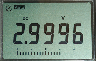
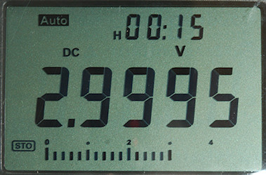
Voltage input has the usual input resistor (R21 & R39: 2×5Mohm) and also a direct connection to the relay (HFD2/003-M-L2-D). The relay is a latching relay with two toggle contacts, this means a pulse will change position and no power is needed to hold the position, this is very useful for battery powered equipment. Both contact are in parallel and only one position is used to route around the input resistor. The signal goes to the PTC (PTC1) and a resistor (R14: 910k). After the PTC is a transistor pair (Q6 & Q7) for protection.
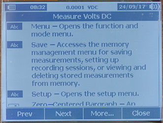
The chips are the main multimeter IC under the black blob, a reference (DZ1: ICL8069), a EEPROM (IC1: K24C08) and a microprocessor (U2: Without code) to translate the switches and input sense to range switch coding.
At the top of the circuit board is the NCV antenna with some pull down resistor (R26, R33, R34: 3×20Mohm).

DSC_9902

DSC_9903DSC_9905

DSC_9904

DSC_9900

This side only has the pads for switches and the LCD display. The LCD pads are fairly large, meaning the placement of the LCD display are fairly uncritical.
DSC_9906


Conclusion

The CAT rating is, as usual, way to high, a meter with 250V fuses cannot be rated for 600V or 1000V.
This meter has a different design with a black LCD and no rotary switch, the functions are about the same as many other meters and is a good standard meter (Except mA range is missing), there are no advanced functions.
Because the backlight must be on at all times, the battery do not last as long. The display can be difficult to see in bright sunlight.

The meter is a nice hobby meter, but the real reason to get it is for the design (If you like it).
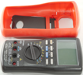


Notes

This meter may exist with many different names on it and small variations in functions.
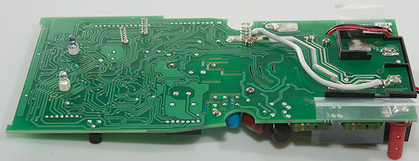
How do I review a DMM
More DMM reviews

My website with reviews of many chargers and batteries (More than 1000): https://lygte-info.dk/

Viewing all 227 articles
Browse latest View live