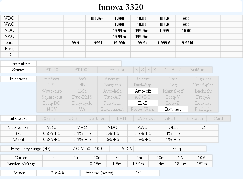
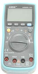
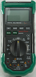
DMM UNI-T UT33A+
Image may be NSFW.
Clik here to view.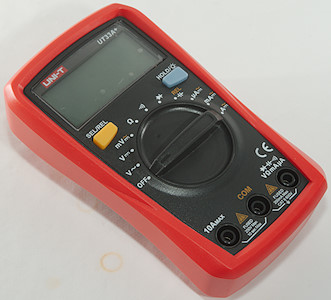
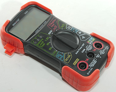
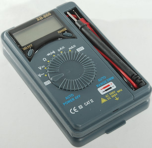
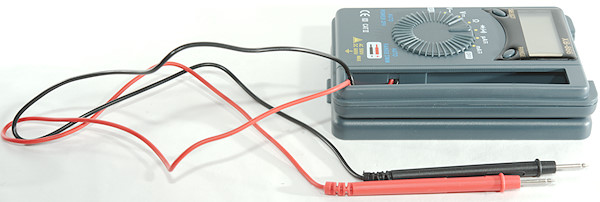
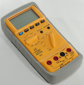
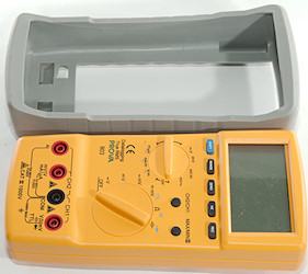
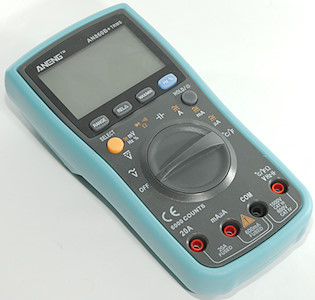
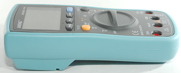
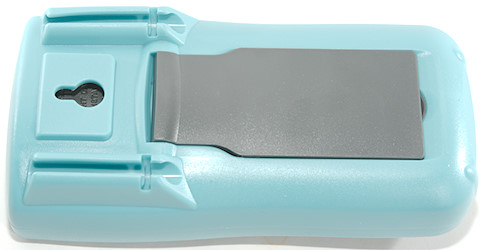
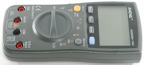
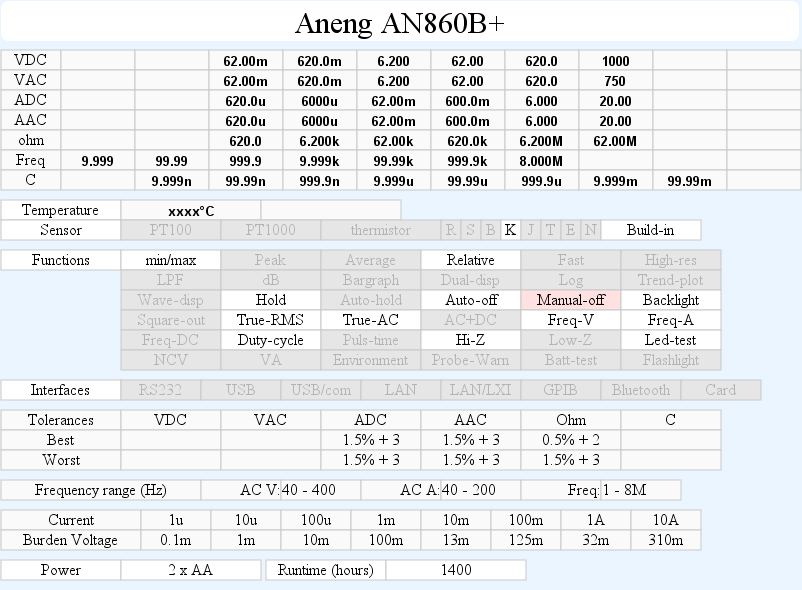
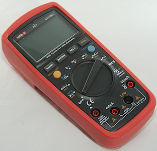
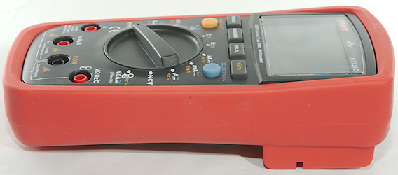
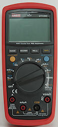
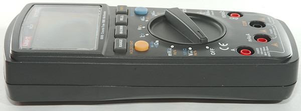
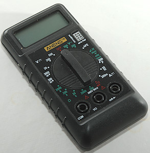
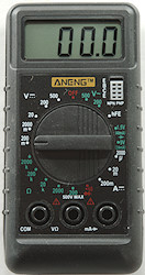
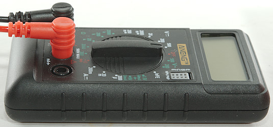
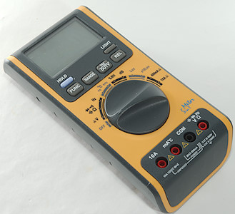
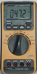
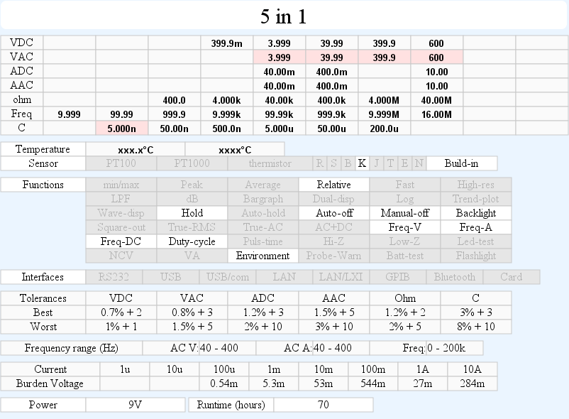
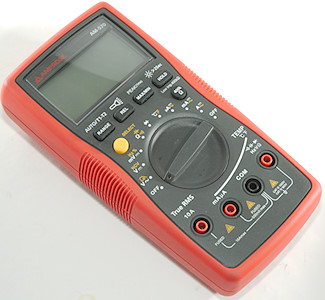
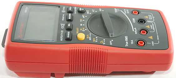
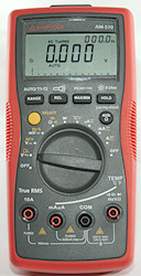
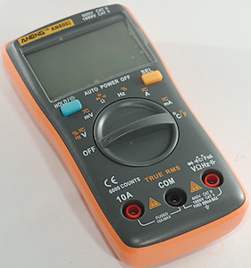
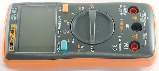
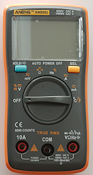
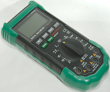
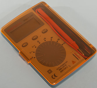
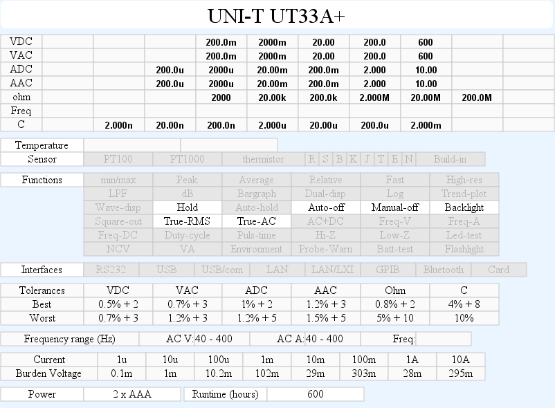
This is a fairly simple and small DMM, but has a nice selection of ranges.
Image may be NSFW.
Clik here to view.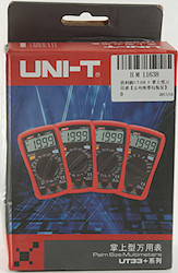 Image may be NSFW.
Clik here to view. Image may be NSFW.
Clik here to view.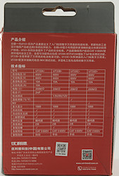 Image may be NSFW.
Clik here to view.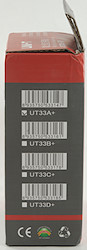
Image may be NSFW.
Clik here to view.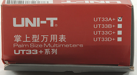
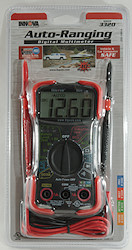
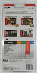
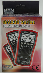
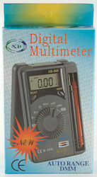
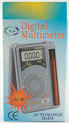
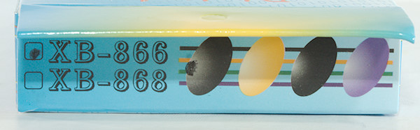
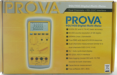
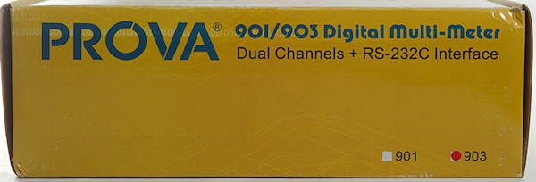
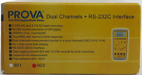
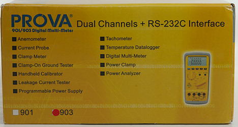
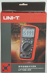
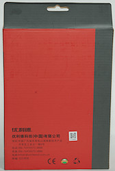
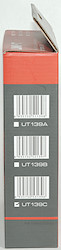
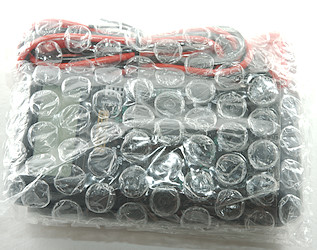
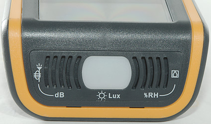
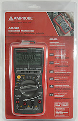
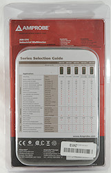
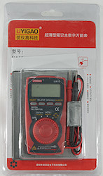
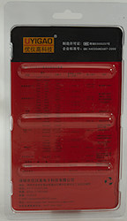
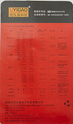
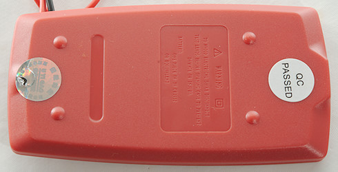
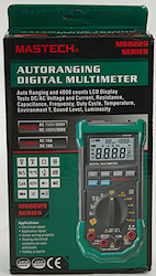
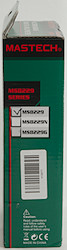
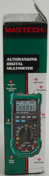
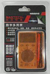
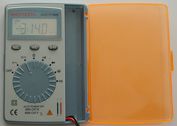
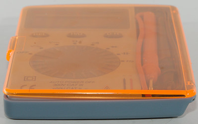
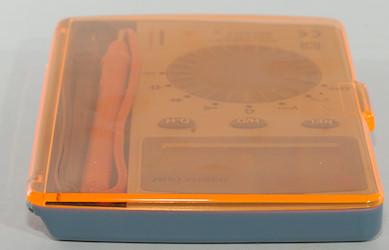
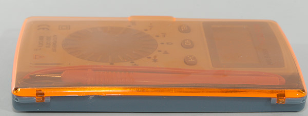
The box is for all the UT33 meters with a checkmark for the actual model and a table on the back for comparing the models (in Chinese).
If you want all the function, you must buy all the models, none of them can everything.
Image may be NSFW.
Clik here to view.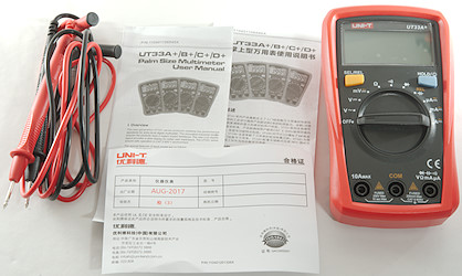
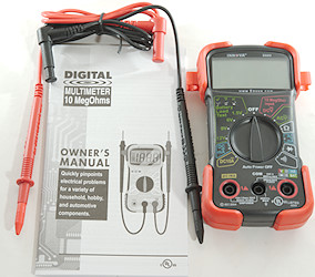
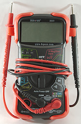
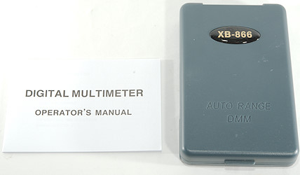
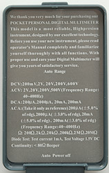
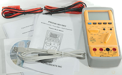
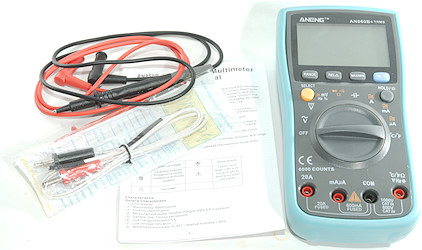
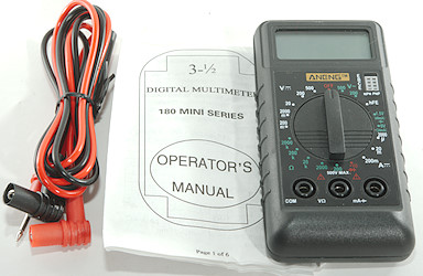
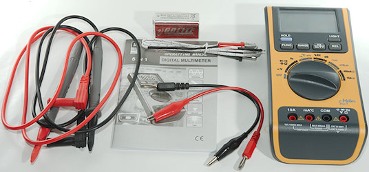
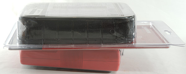
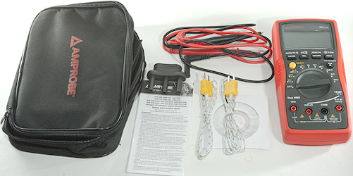
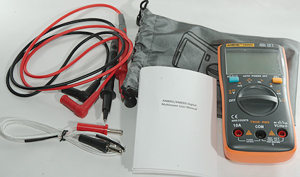
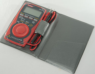
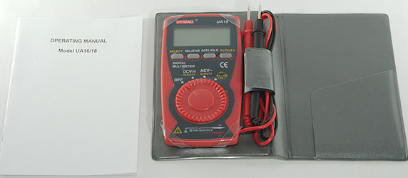
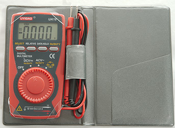
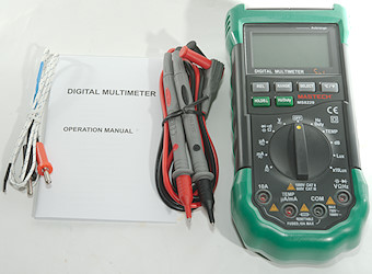
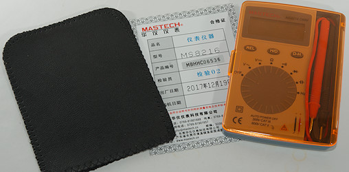
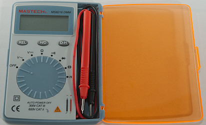
In the box was the meter, probe leads and a instruction sheet in both Chinese and English. The instruction sheet is for all four models in the series (A, B, C, D).
Image may be NSFW.
Clik here to view.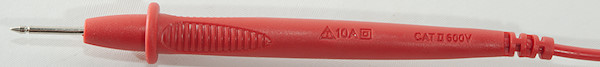
Image may be NSFW.
Clik here to view.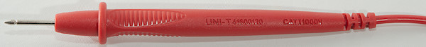
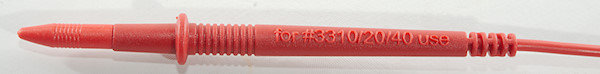
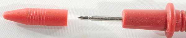
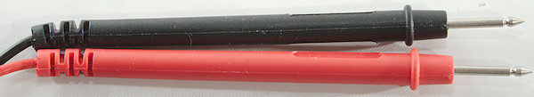
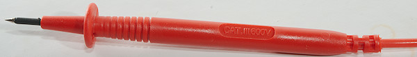
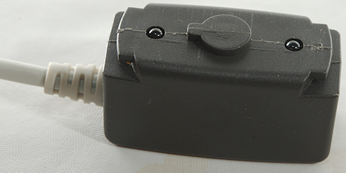
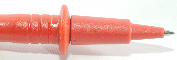
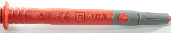
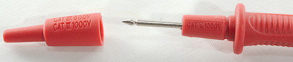
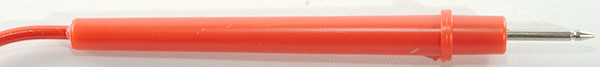
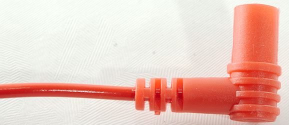
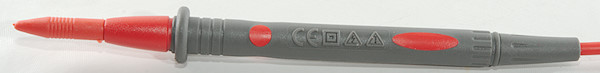
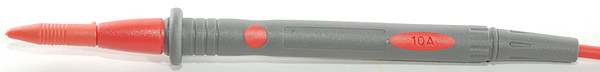
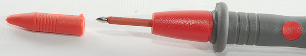
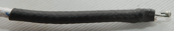
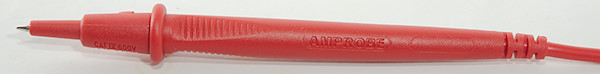
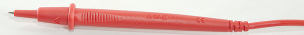
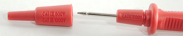
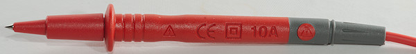
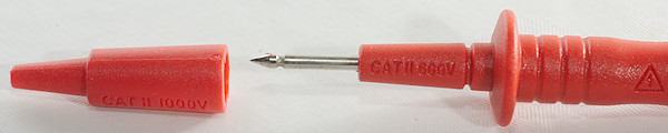
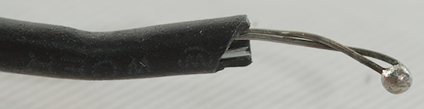
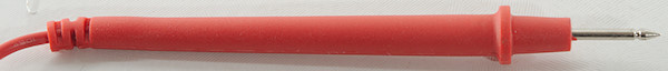
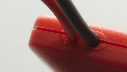
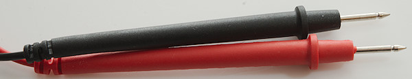
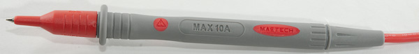
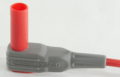
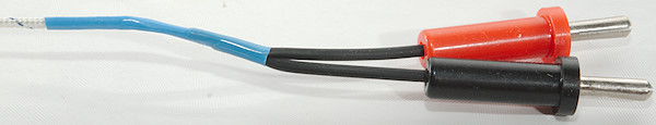
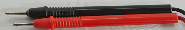
The standard probes are about normal size, but rating them for 10A is on the optimistic side.
Image may be NSFW.
Clik here to view.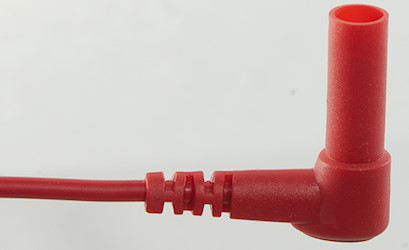
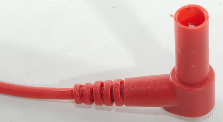
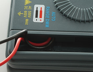
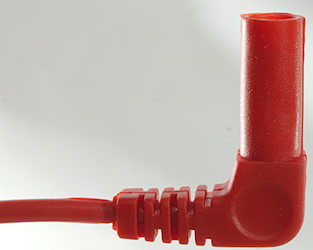
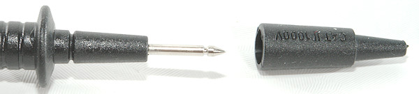
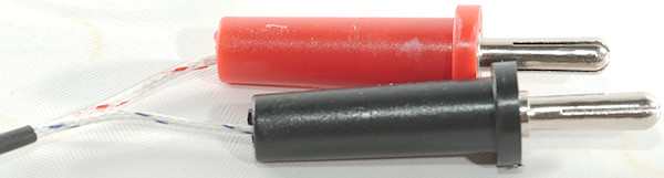
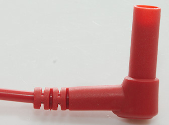
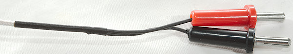
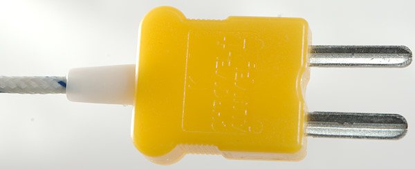
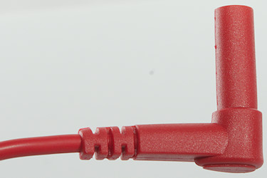
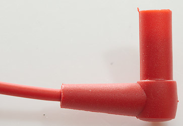
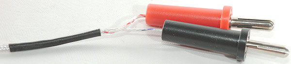
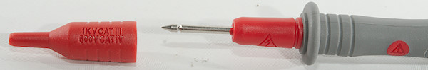
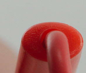
The plugs are fully shrouded.
Image may be NSFW.
Clik here to view.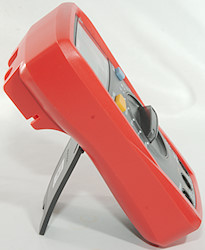 Image may be NSFW.
Clik here to view.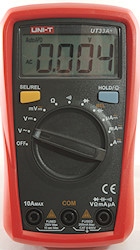
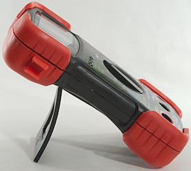
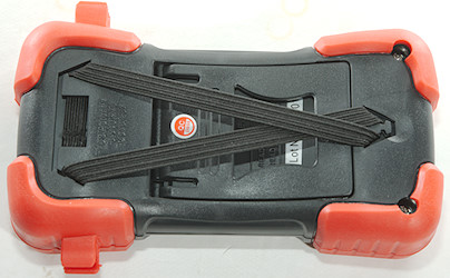
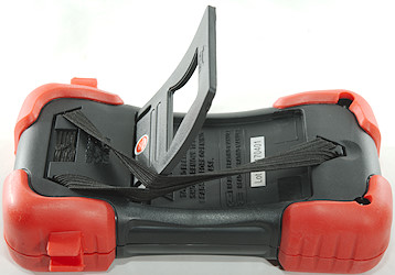
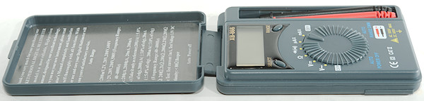
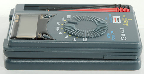
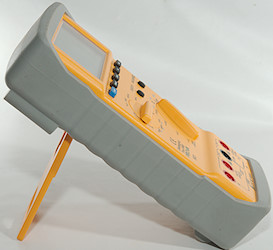
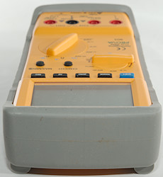
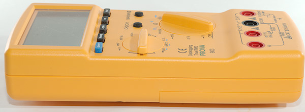
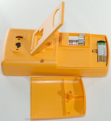
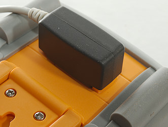
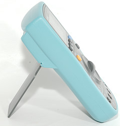
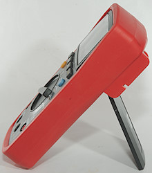
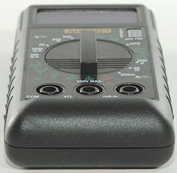
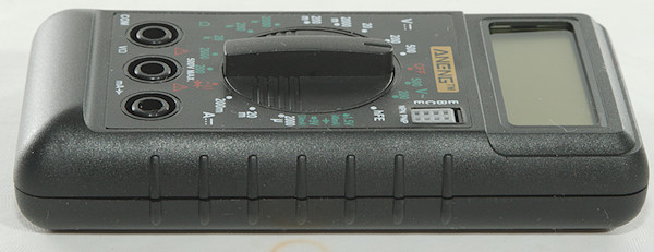
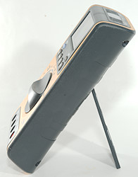
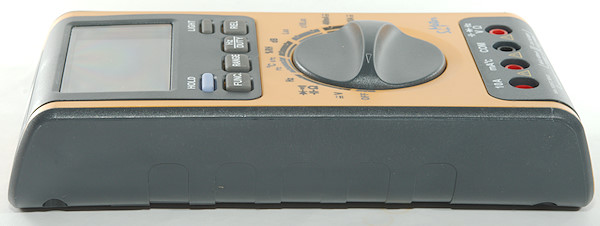
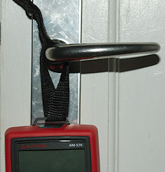
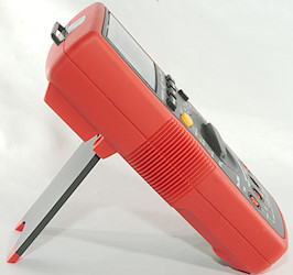
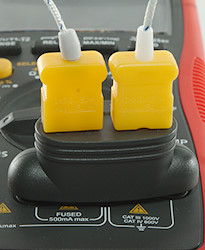
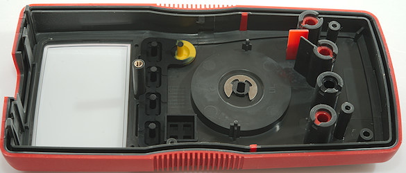
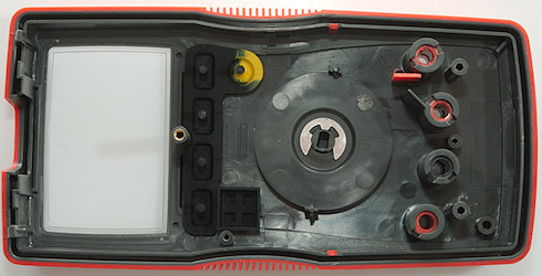
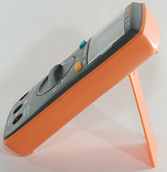
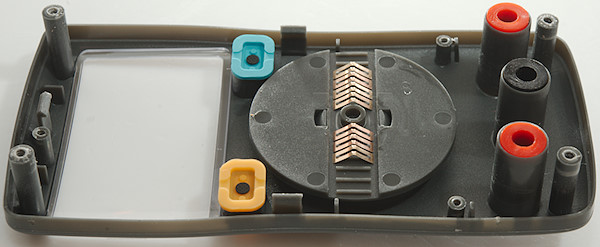
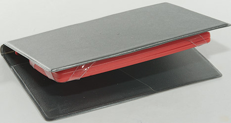
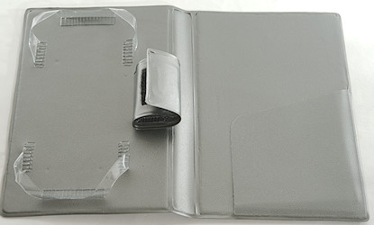
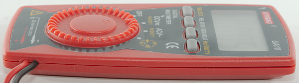
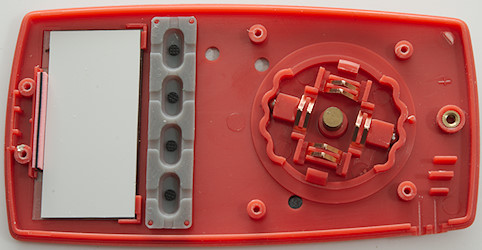
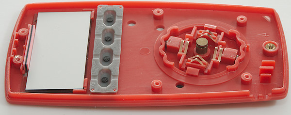
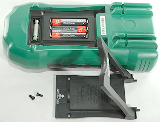
With the meter lying flat it is possible to turn the switch, but on the tilting bale it will slide around.
Image may be NSFW.
Clik here to view.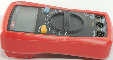
Image may be NSFW.
Clik here to view.
Image may be NSFW.
Clik here to view.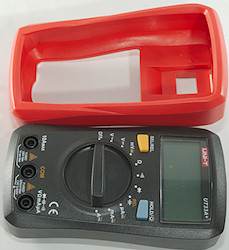
Image may be NSFW.
Clik here to view.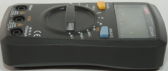
Image may be NSFW.
Clik here to view.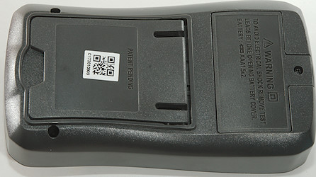
Image may be NSFW.
Clik here to view.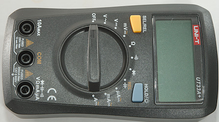
Image may be NSFW.
Clik here to view.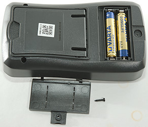
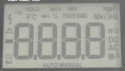
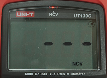
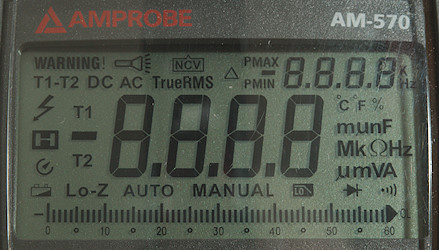
Display
Image may be NSFW.
Clik here to view.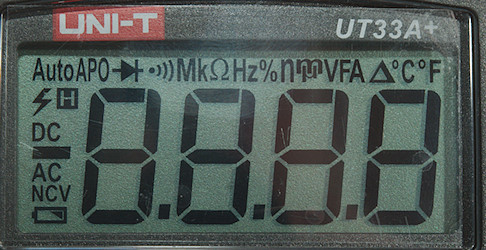
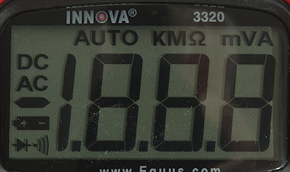
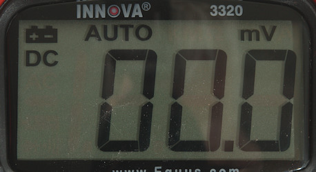
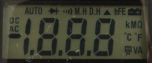
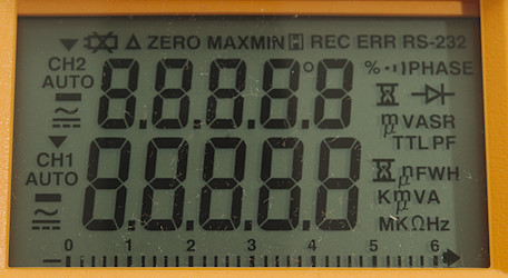
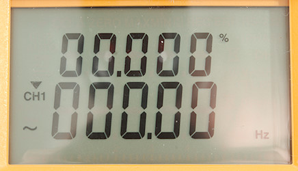
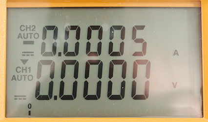
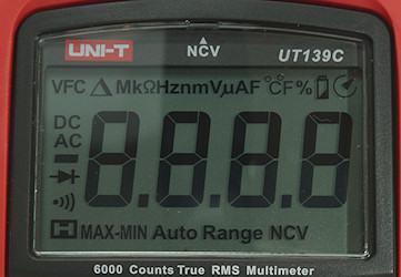
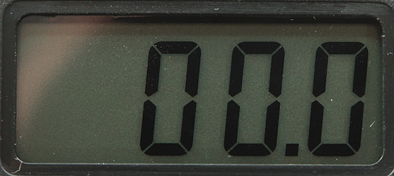
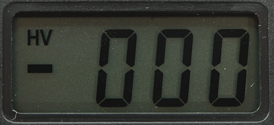
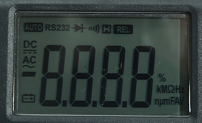
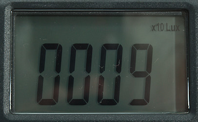
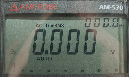
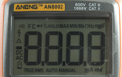
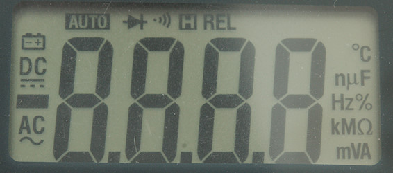
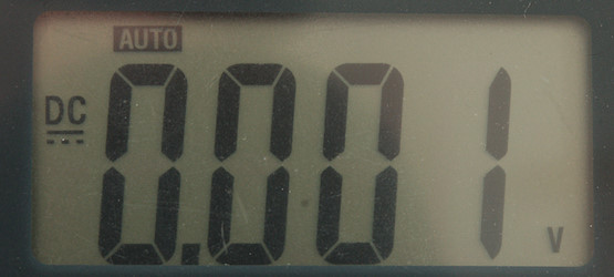
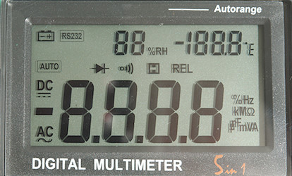
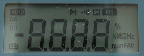
All the segments are shown during power on, not all are used by this meter.
Image may be NSFW.
Clik here to view.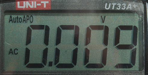
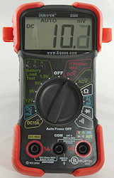
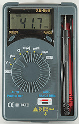
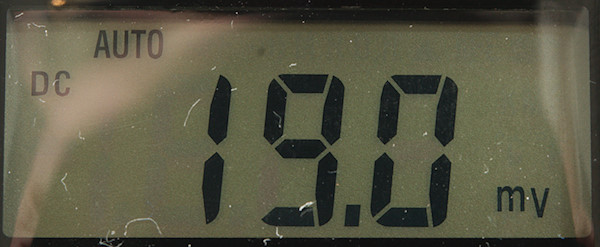
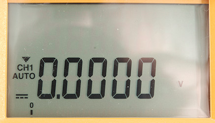
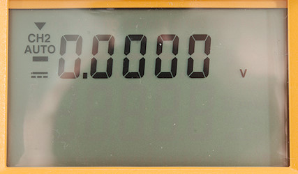
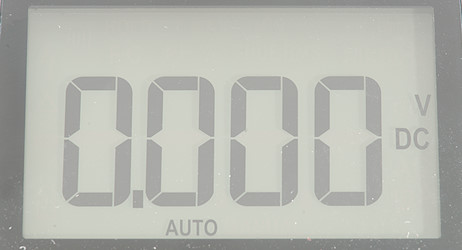
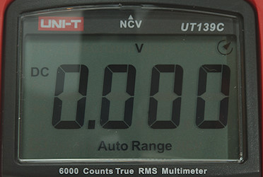
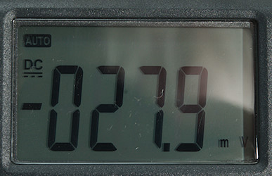
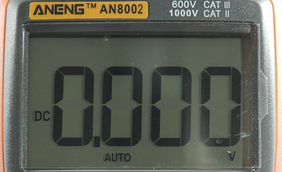
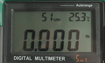
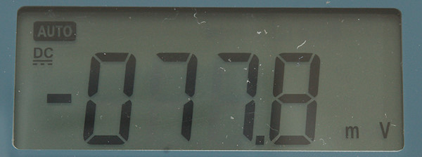
Typical display during usage, it will show the number and selected measurement
Functions
Image may be NSFW.
Clik here to view.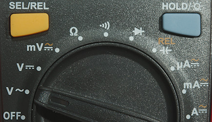
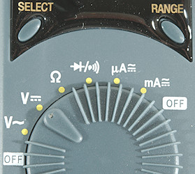
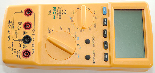
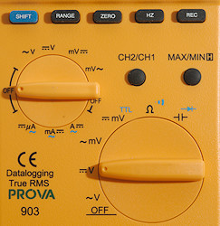
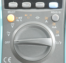
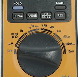
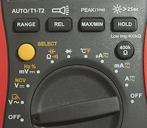
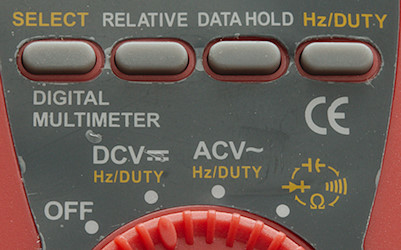
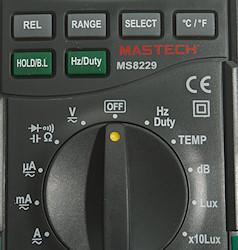
Buttons:
- Sel/rel: Used to select AC in mV and current ranges and to zero capacity range.
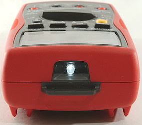
- Hold/Backlight: Will freeze the display reading, until pressed again. Hold down to turn backlight on.
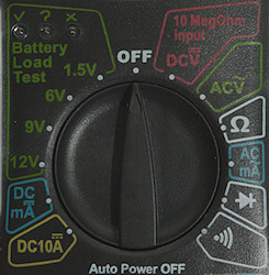
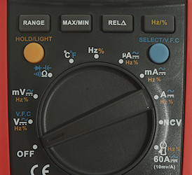
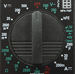
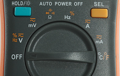
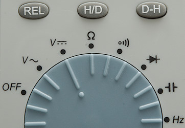
Rotary switch:
- Off: Meter is turned off
- VAC: AC Voltage
- VDC: DC Voltage
- mV: Milli volt AC and DC, use SEL to select.
- Image may be NSFW.
Clik here to view.![ohm]() : Resistance range.
: Resistance range. - Image may be NSFW.
Clik here to view.![Cont]() : Continuity range.
: Continuity range. - Image may be NSFW.
Clik here to view.![diode]() : Diode range.
: Diode range. - Image may be NSFW.
Clik here to view.![cap]() : Capacitance range, use REL to zero before measuring low values.
: Capacitance range, use REL to zero before measuring low values. - uA: Micro ampere range, use SEL to select AC.
- mA: Milli ampere range, use SEL to select AC.
- A: Ampere range, use SEL to select AC.


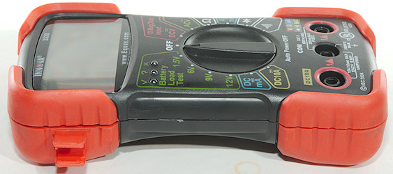
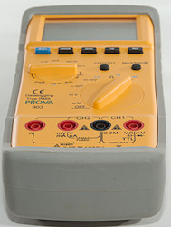
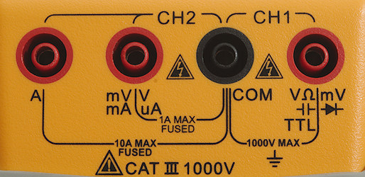
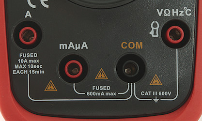
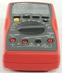
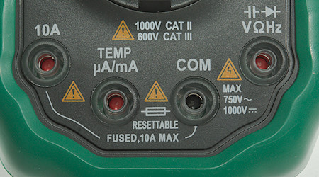
Input
Image may be NSFW.
Clik here to view.
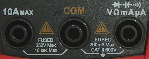
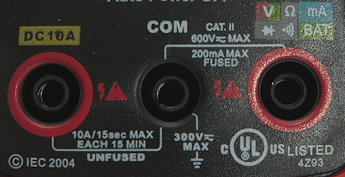
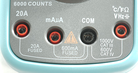
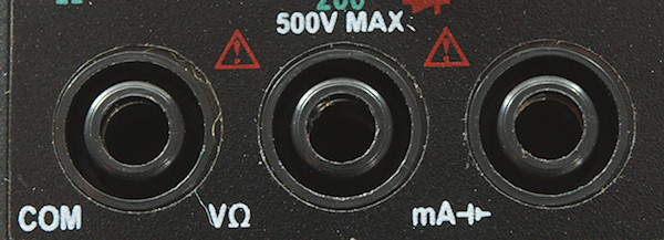
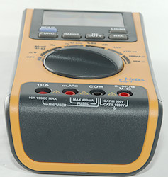
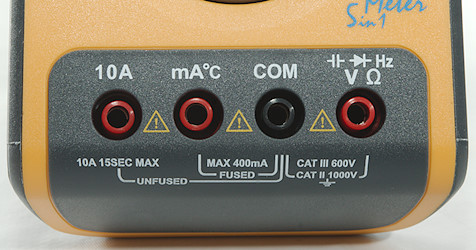
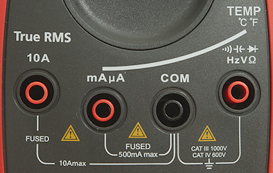
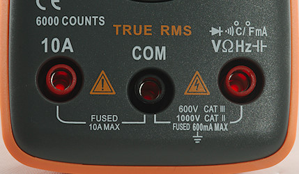
- 10ADC: 10A DC current input.
- COM: The common terminal for all ranges.
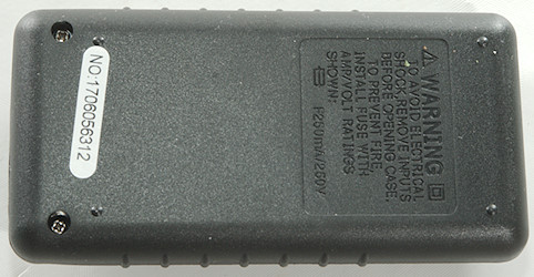
- xxx: All other ranges, including mA. It is always problematic when a current range shares connector with a voltage range, if the switch is in the wrong position the fuse will blow (at least). This will only affect current, voltage will still work.
Measurements
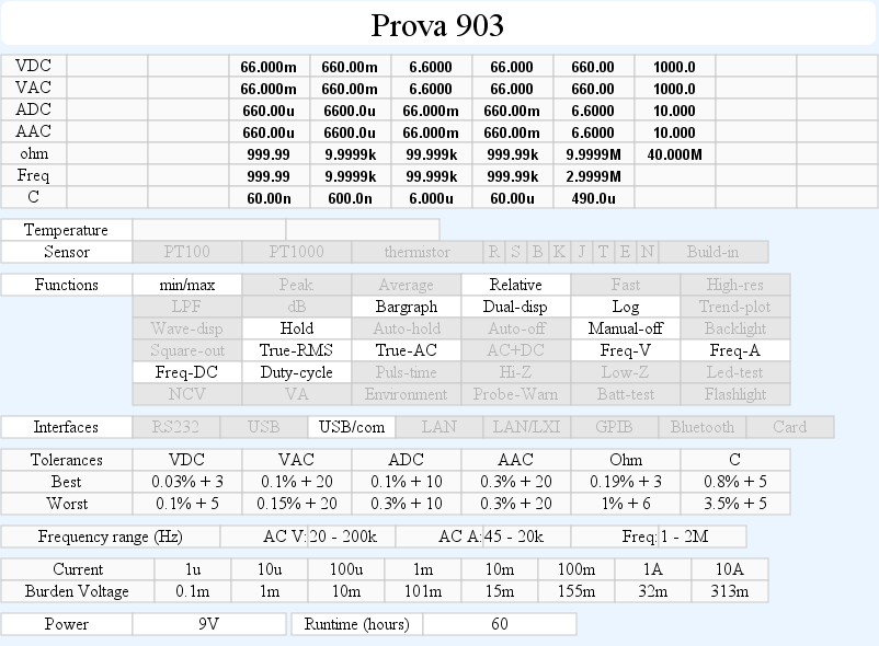
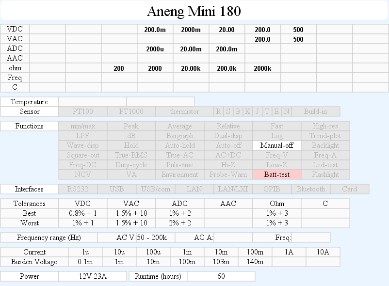
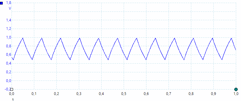
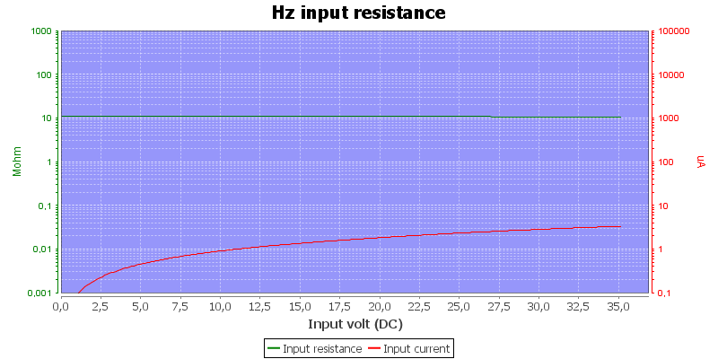
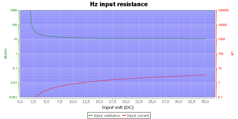
- Volt and frequency
- 1V AC readings is 5% down at 2.5kHz
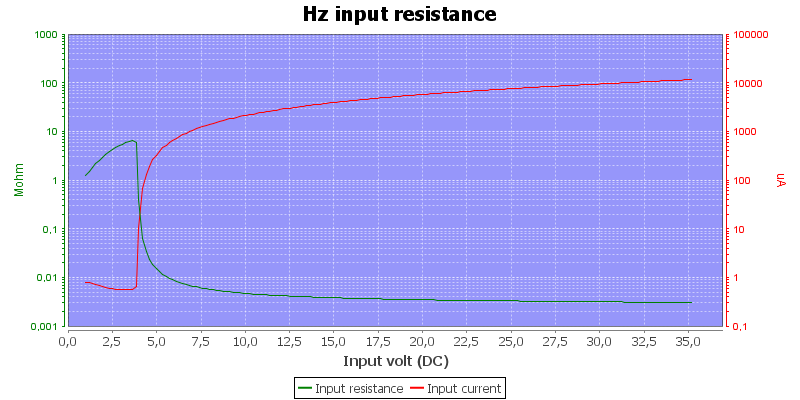
- Input impedance is 10-11Mohm on DC and AC
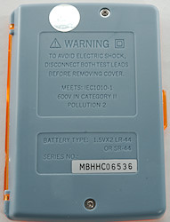
- Input protection is 600V AC/DC
- 1V AC readings is 5% down at 2.5kHz
- Current
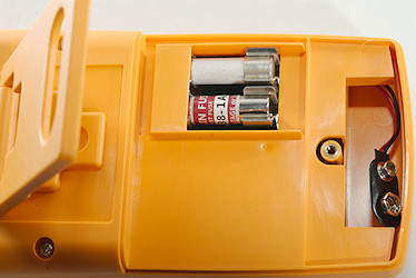
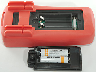
- 10A range is fused with a 10A/250V 5×20mm fuse
- mA range is fused with a 0.2A/250V 5×20mm fuse
- 10A range has an audible alarm at 10A or above.
- 10A range is fused with a 10A/250V 5×20mm fuse
- Ohm, continuity, diode and capacity
- Ohm needs about 3.5s to measure 100ohm
- Ohm voltage is 1V open and 0.31mA shorted
- Continuity is fast (About 20ms).
- Continuity beeps when resistance is below 31ohm.
- Continuity is 2.1V open and 0.31mA shorted
- Diode range uses 2.2V, max. display is 1.999V at 0.07mA, max. current is 0.9mA shorted
- 2000uF takes about 9 seconds to measure.
- Overload protection is 600V AC/DC
- Ohm needs about 3.5s to measure 100ohm
- Miscellaneous
- Current consumption of meter is 1.2 to 1.6mA (15.5mA with backlight).
- Display gets unstable about 1.6V, but it might show overflow before, battery symbol show at 2.4V.
- Readings will be correct down to 2.4V, below that they can be high or display can show OL
- Backlight works down to 1.6V
- Viewing angle is good, except from the top
- Display updates around 2.5 times/sec
- Backlight will turn off in about 30 seconds.
- Will automatic turn power off in about 15 minutes.
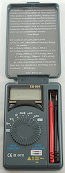
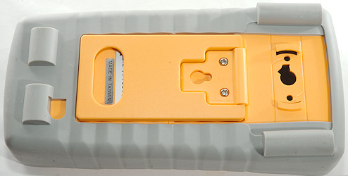
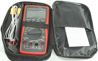
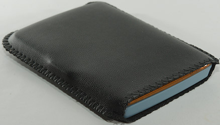
- Standard probes fits in the meter.
- The meter usual need a couple of display update to reach the final value.
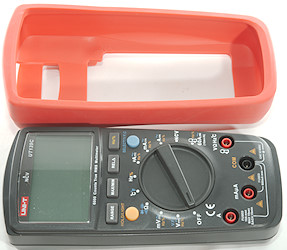
- Weight is 208g without accessories, but with sleeve and batteries.
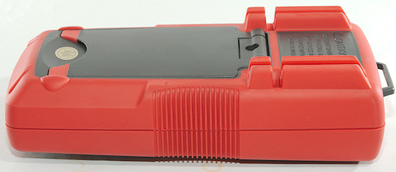
- Size is 135 × 77 × 47mm
- Current consumption of meter is 1.2 to 1.6mA (15.5mA with backlight).
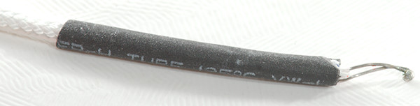
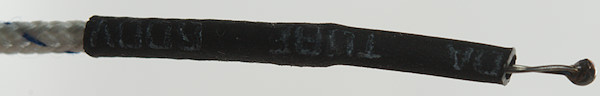
- Probes
- Probe resistance 72mOhm for one, that is fairly high.
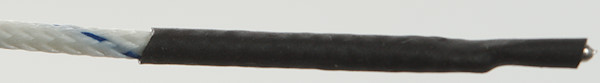
- Probe wire is a bit thin, the are 89cm long.
- Probe resistance 72mOhm for one, that is fairly high.
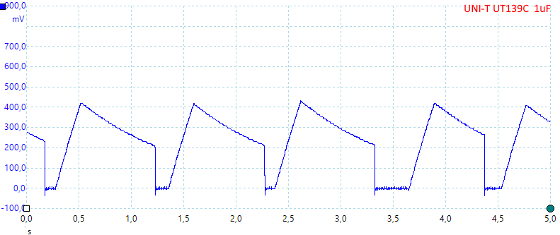
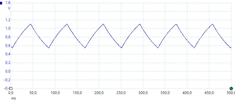
Image may be NSFW.
Clik here to view.
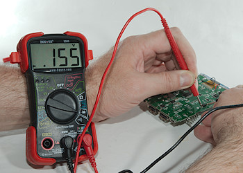
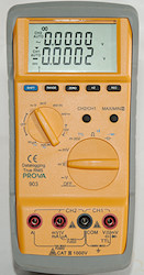
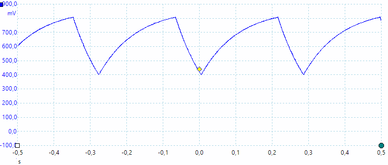
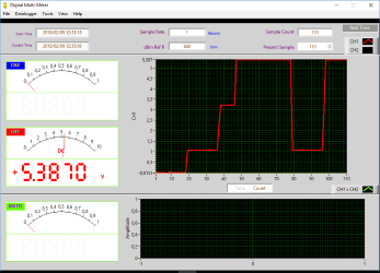
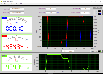
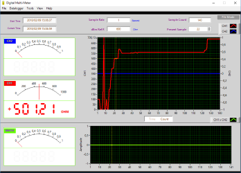
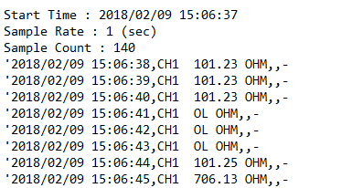
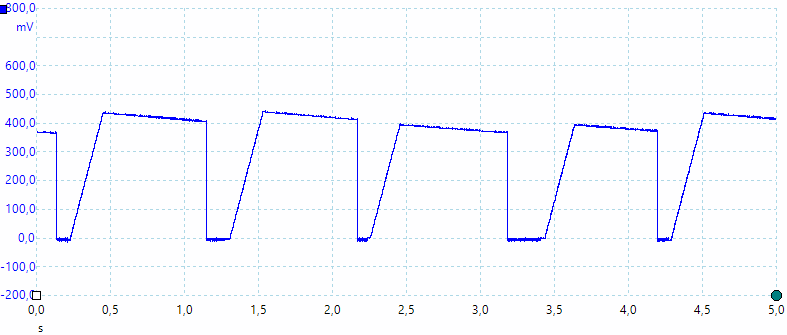
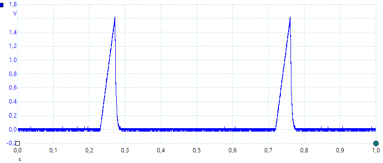
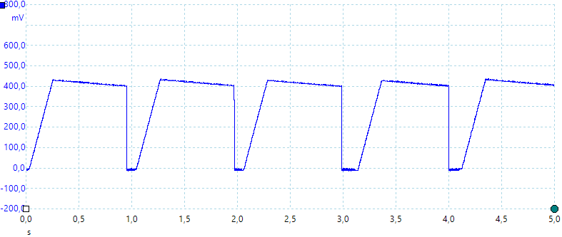
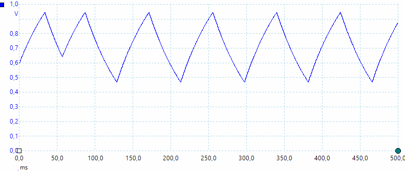
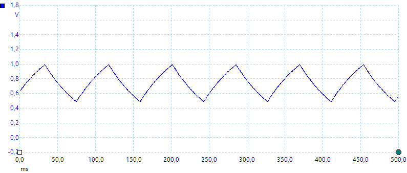
The meter is a true-rms meter.
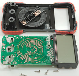
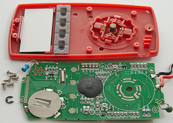
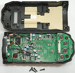
Tear down
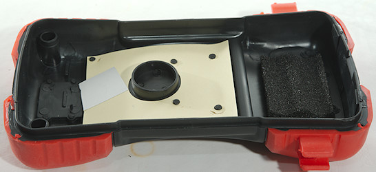
Image may be NSFW.
Clik here to view.
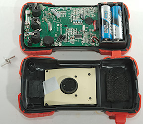
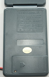
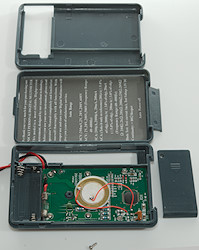
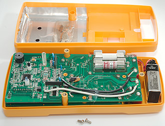
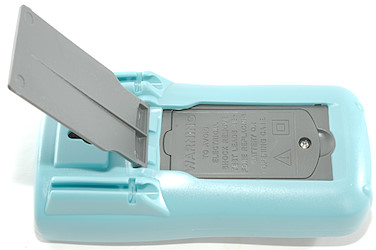
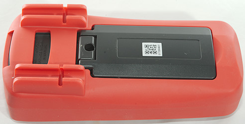
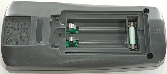
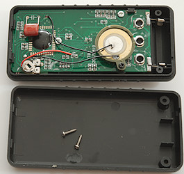
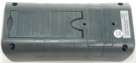
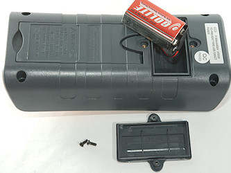
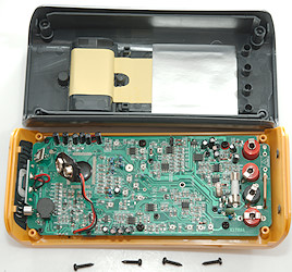
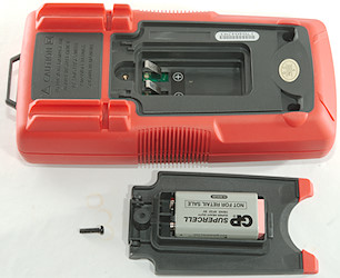
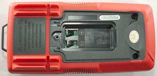
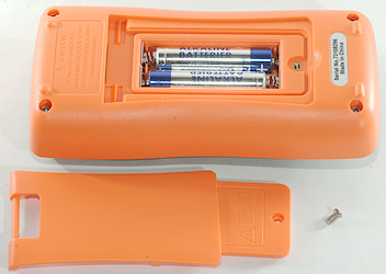
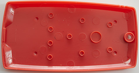
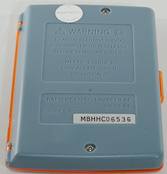
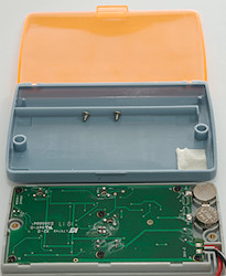
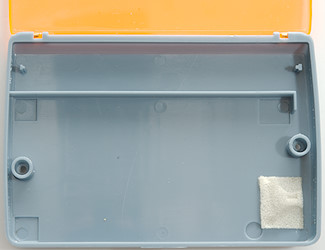
I had to remove two screws, the battery cover could stay on.
Image may be NSFW.
Clik here to view.
Image may be NSFW.
Clik here to view.
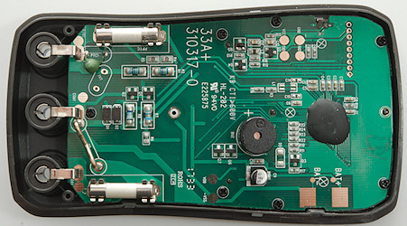
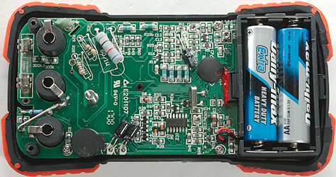
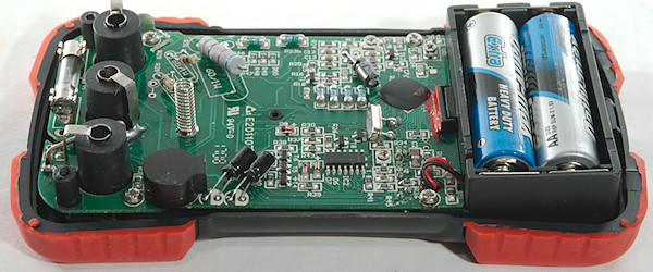
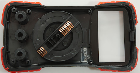
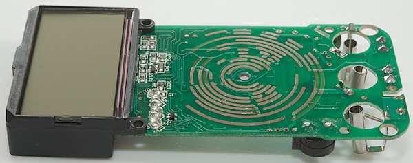
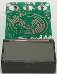
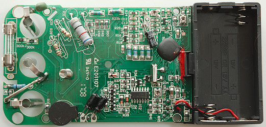
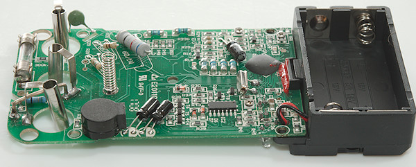
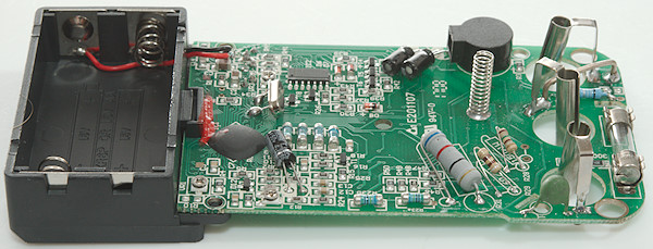
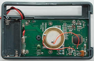
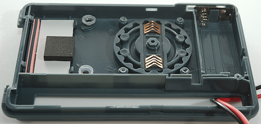
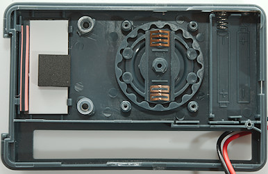
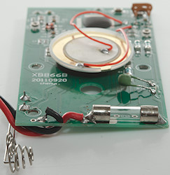
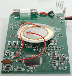
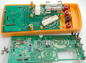
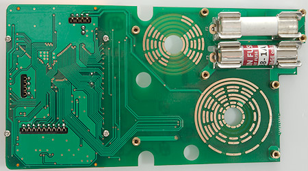
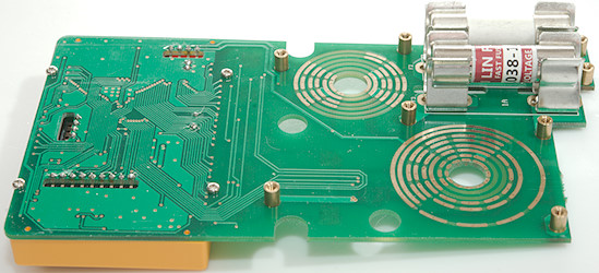
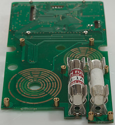
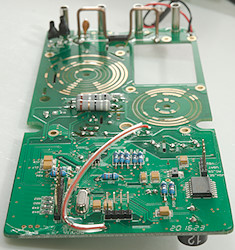
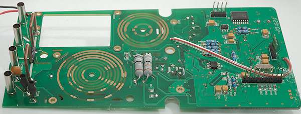
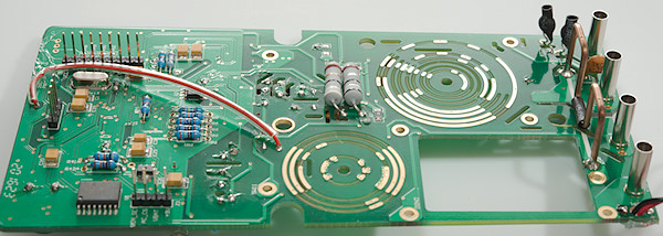
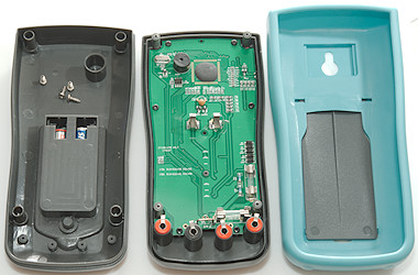
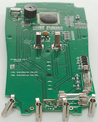
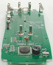
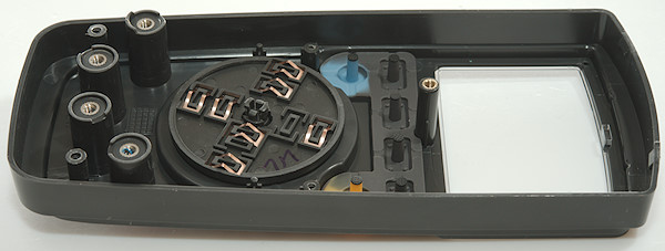
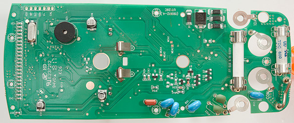
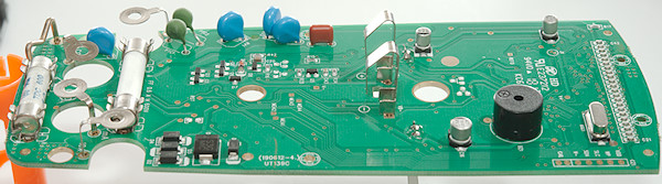
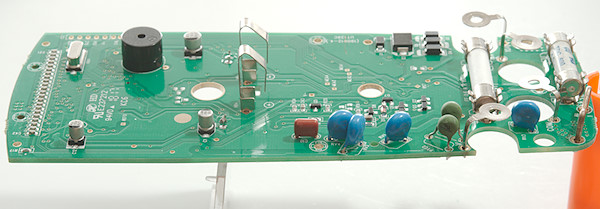
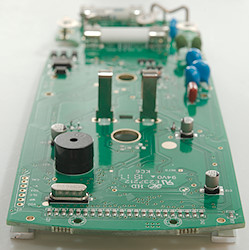
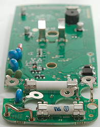
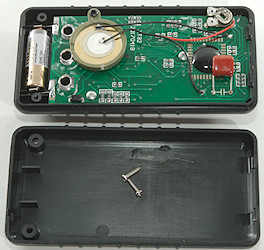
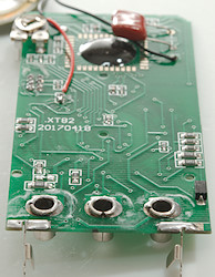
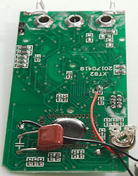
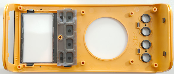
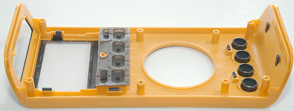
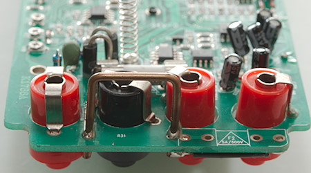
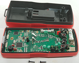
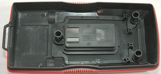
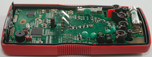
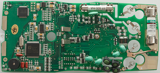
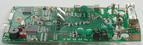
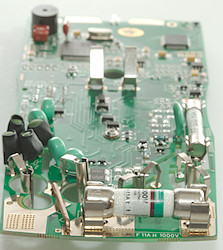
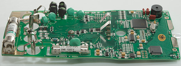
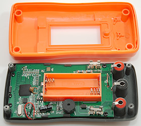
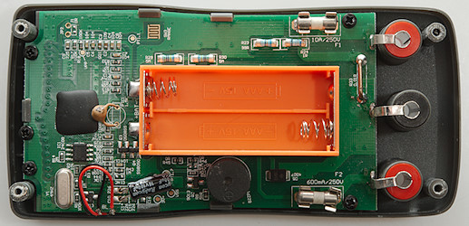
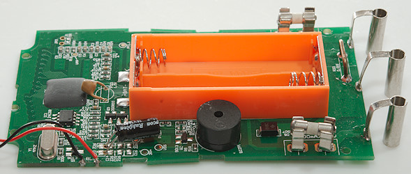
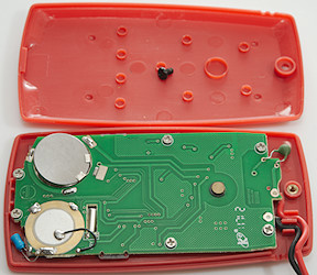
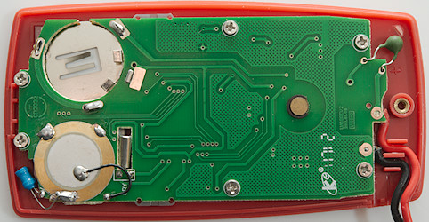
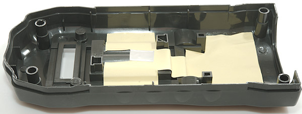
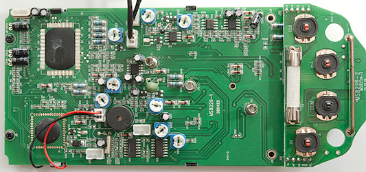
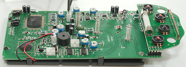
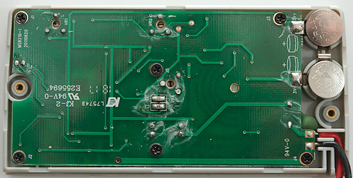
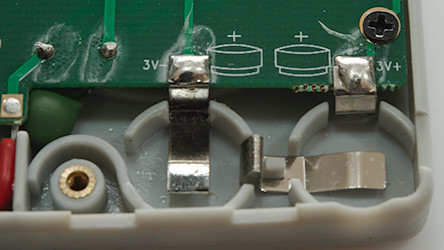
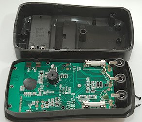
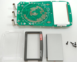
The circuit board is shaped to fit the box and uses ceramic fuses.
Image may be NSFW.
Clik here to view.
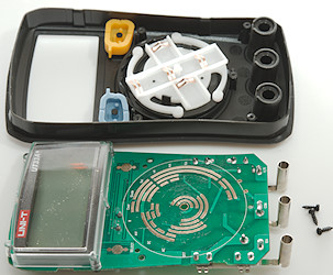
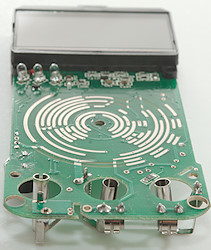
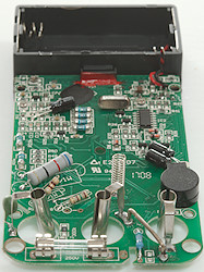
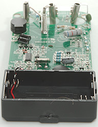
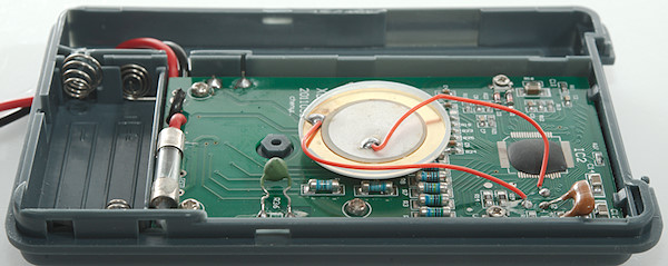
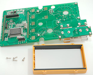
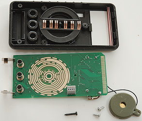
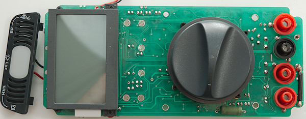
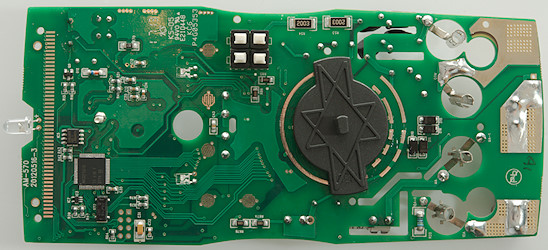
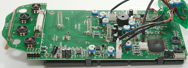
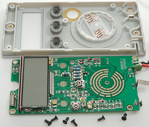
I had to remove 3 screws around the range switch to get the circuit board out.
Image may be NSFW.
Clik here to view.
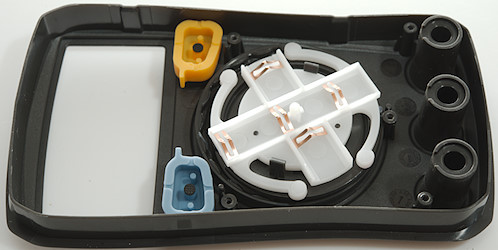
Image may be NSFW.
Clik here to view.
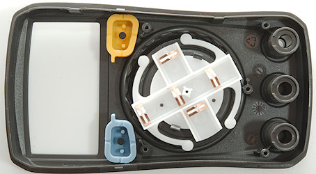
Image may be NSFW.
Clik here to view.
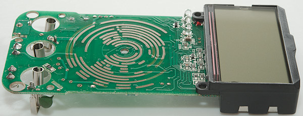
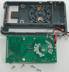
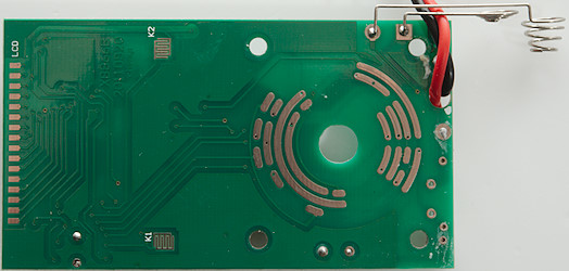
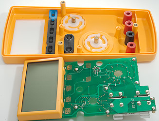
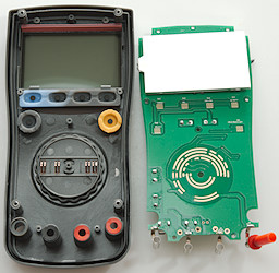
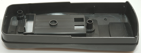
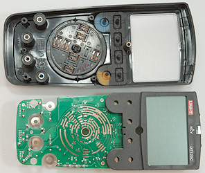
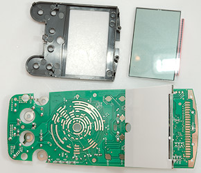
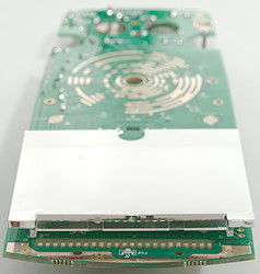
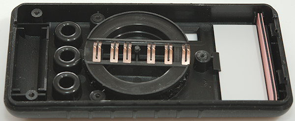
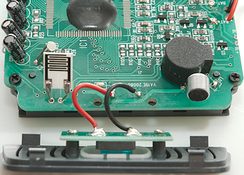
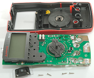
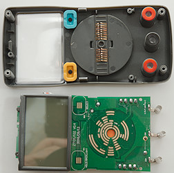
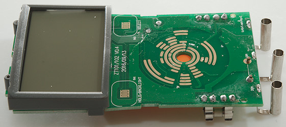
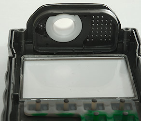
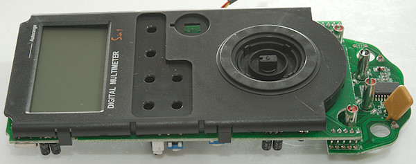
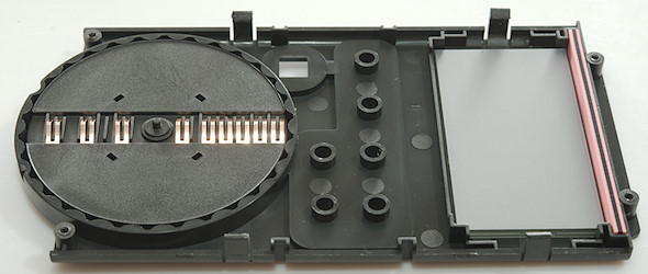
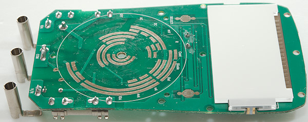
And four screws to remove the lcd display, the backlight is soldered to the circuit board.
Image may be NSFW.
Clik here to view.
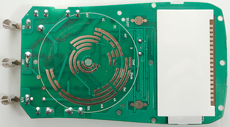
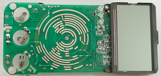
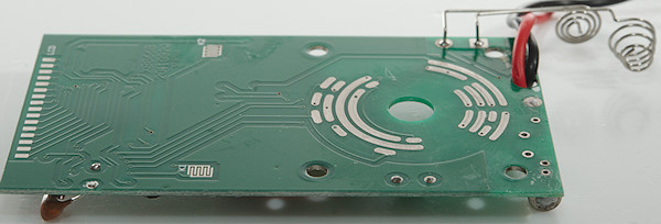
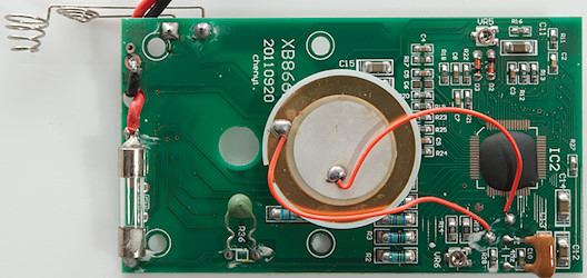
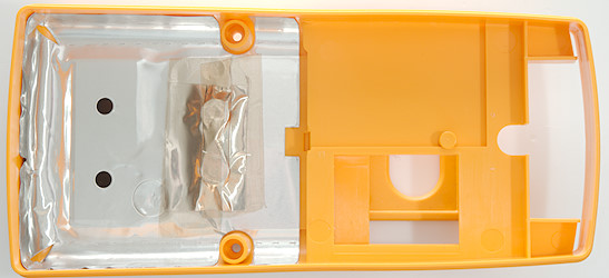
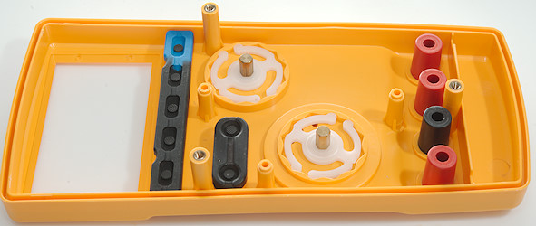
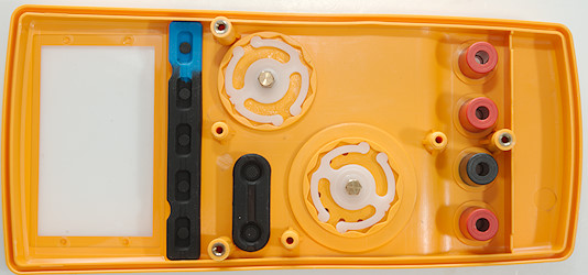
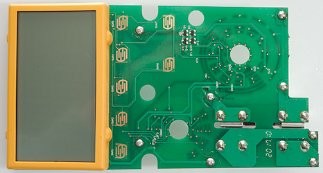
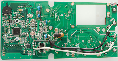
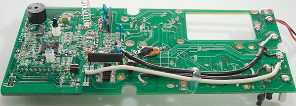
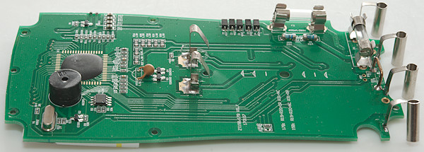
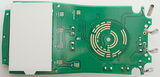
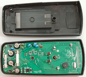
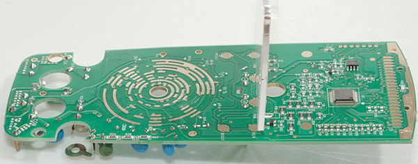
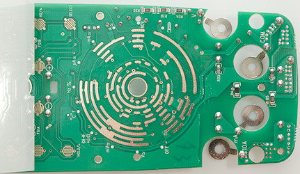
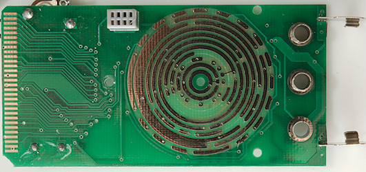
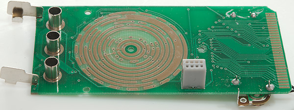
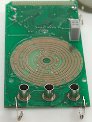
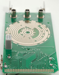
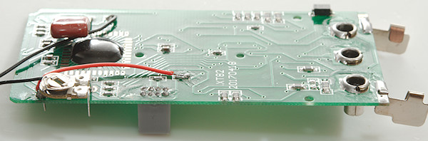
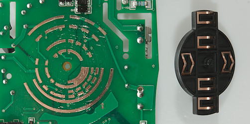
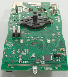
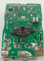
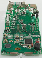
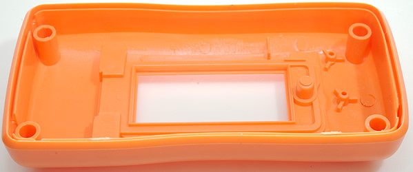
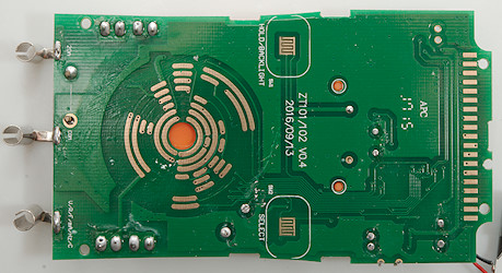
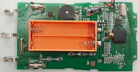
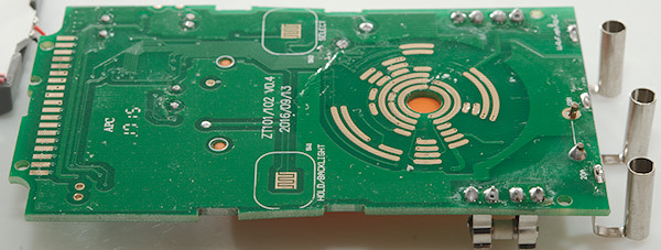
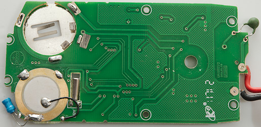
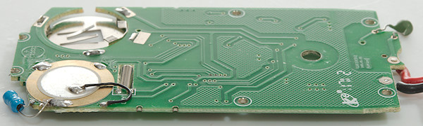
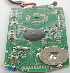
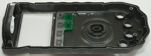
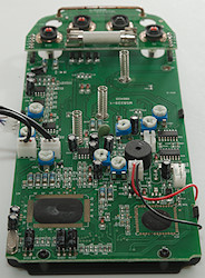
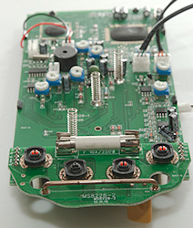
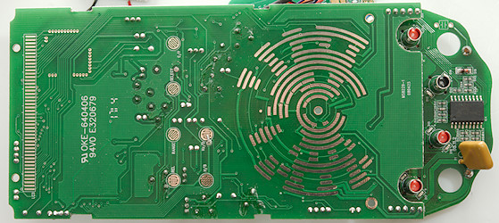
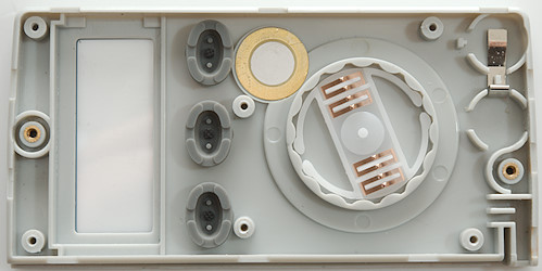
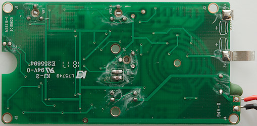
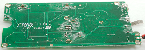
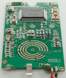
There is no parts on this side, only pads for switches and lcd display and a marking of where ranges.
Image may be NSFW.
Clik here to view.
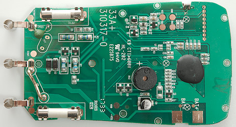
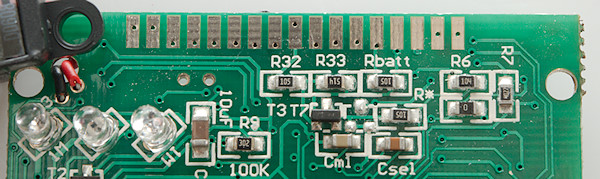
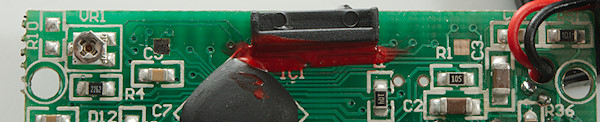
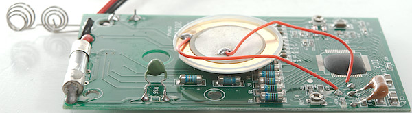
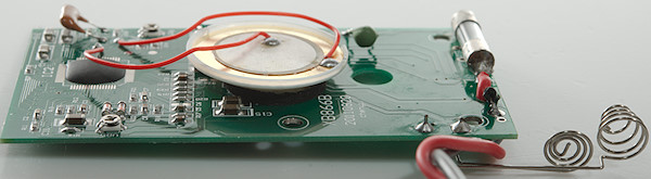
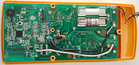
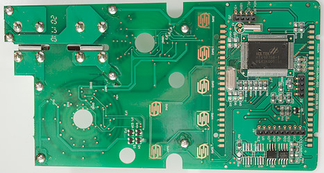
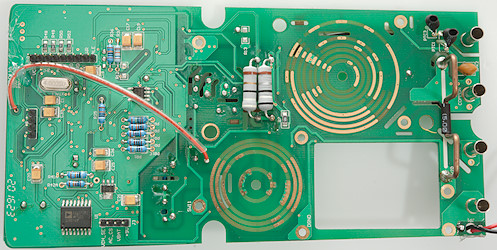
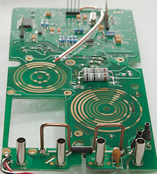
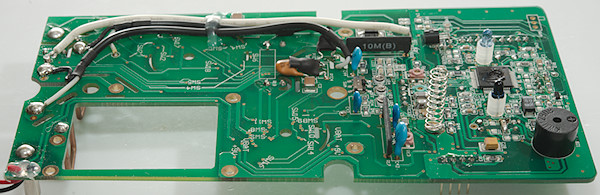
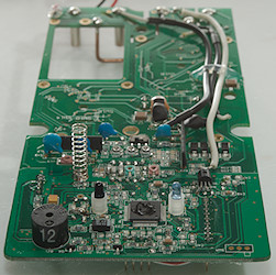
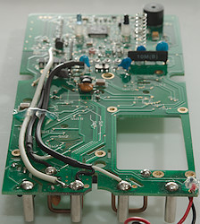
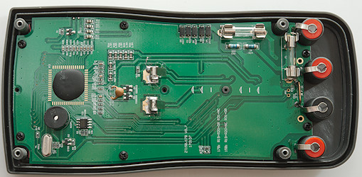
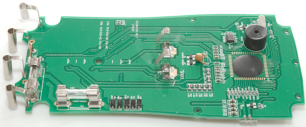
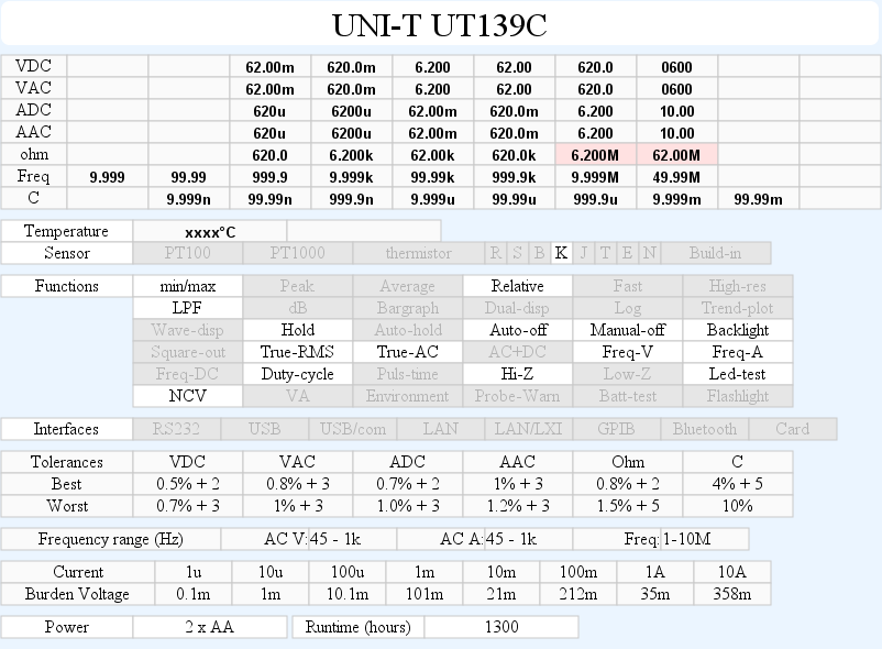
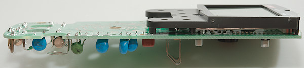
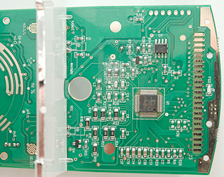
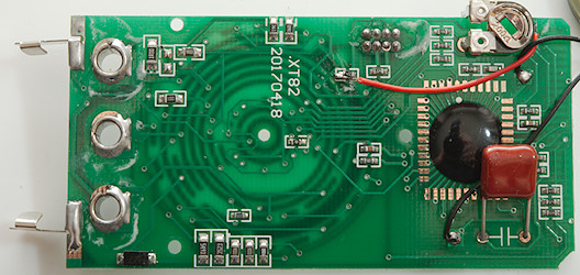
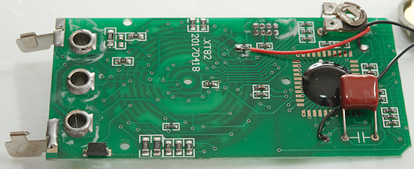
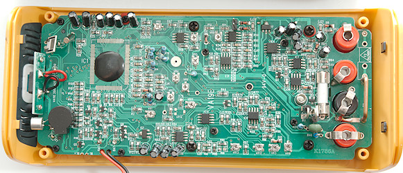
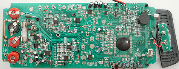
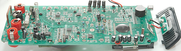
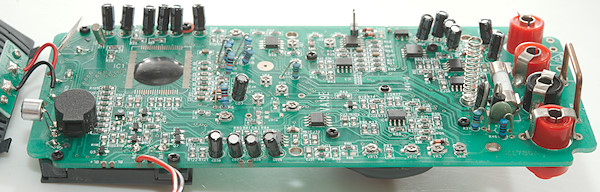
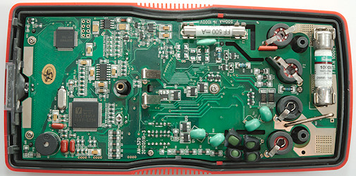
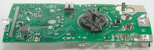
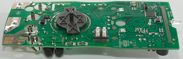
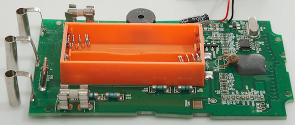
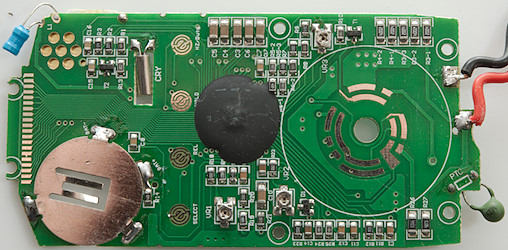
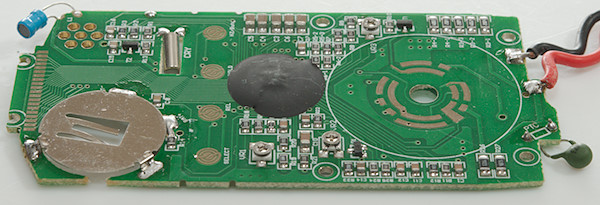
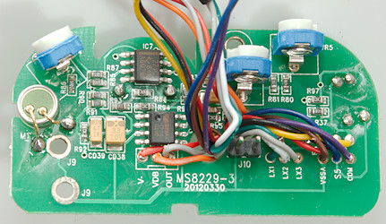
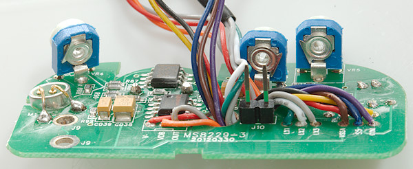
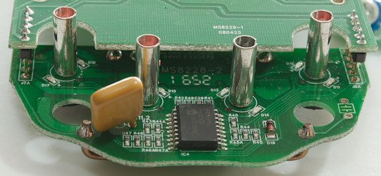
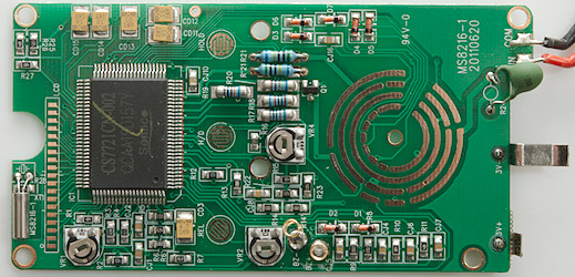
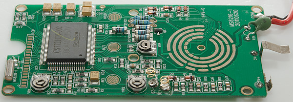
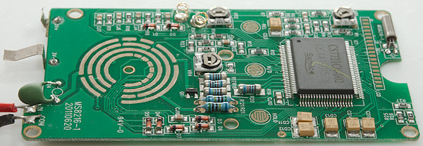
The resistor for the uA range (R7: 99ohm) and uA range (R8: 0.99ohm) is protected by two diodes (D1 & D2: M7). The main input shunt is two resistors (R1 & R2: 2×5Mohm), there is also a secondary input chain (R4 & R5: 2X499kOhm). Ohm output is protected by a PTC (PTC1) and two transistors (Q1 & Q2).
The multimeter IC is a COP (Chip on board) that is bonded directly to the circuit board and then covered with some black stuff.
Image may be NSFW.
Clik here to view.
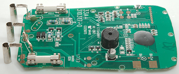
Image may be NSFW.
Clik here to view.
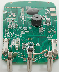 Image may be NSFW.
Clik here to view.
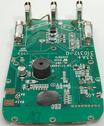
Image may be NSFW.
Clik here to view.
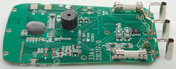
Image may be NSFW.
Clik here to view.
Conclusion
The CAT rating do not match the fuses used, i.e. it is not correct, but at least it use fuses and fairly good ones.
The meter has a nice selection of ranges, but is missing frequency and min/max functions for a general purpose meter. This is the best meter in the UT33+ range, but the other meters in the range each has one function this meter is missing (Battery test, temperature, NCV).
I was a bit surprised that this meter is a true rms meter.
Notes
UNI-T do often make rebranded meters, i.e. it may exist with other names on it.
How do I review a DMM
More DMM reviews
My website with reviews of many chargers and batteries (More than 1000): http://lygte-info.dk/