Multimeter guide
![DSC_4898]()
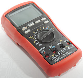
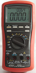
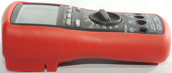
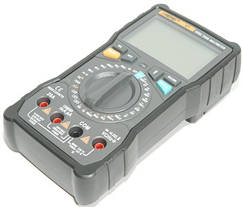
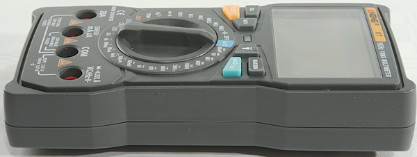
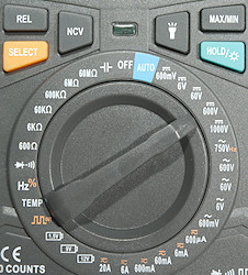
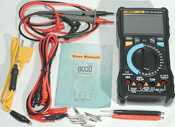
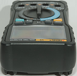
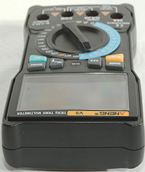
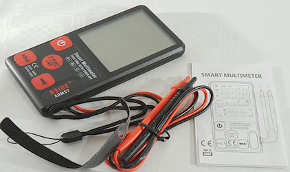
This guide is a simple (but long) guide for many details on multimeters, it do not tell how to make measurements, but explains about the different function on the multimeter. This guide has lot of pictures, each showing a small part of a multimeter to illustrate the functions and differences between meters. Most of the article is about measurement function, but at the end I will also look at a few physical aspects on the meter.
This guide can be very useful to make a list of functions you want in your next multimeter.
Contents
Minimum, maximum and average of a value
Peak or fast minimum, maximum
Freezing the display
Manual selecting range
Selecting function
Background light and flashlight
Frequency and duty cycle
Relative measurements
Auto power off, can it be disabled?
Dual or triple display
Bargraph, sometimes a fast estimate of value
Voltage measurement
Current measurement
Ohm, continuity, diode and capacity measurement
Temperature measurement
Non contact voltage or electric field detection
Low-Z, getting rid of ghost voltages
Low pass filter for variable frequency drives
Turning the meter on or off
Input terminals
Tilting bale or kickstand
Batteries and fuses
Probe holders, need an extra hand
Hanger
Minimum, maximum and average of a value
![DSC_4900minmax]()
![DSC_4902minmax]()
![DSC_4903minmax]()
![DSC_4904minmax]()
![DSC_4905minmax]()
![DSC_4906minmax]()
Many multimeters have a function to record minimum and maximum value, it is fairly slow (0.1 to 1 second), this is necessary to work for AC and not record random noise pulses. This function will usual work on most ranges on the multimeter, except capacity.
Depending on meter is may be possible to show actual value while recording minimum and maximum. Some of the better meters will also calculate a average while recording minimum and maximum. Meters with dual or triple display may use the extra display(s) for some of this.
To activate the function press the button, more presses on the button will change between minimum/maximum/average/actual depending on the meter. To end recording hold down the button. This function will nearly always disable auto ranging, i.e. remember to manually select the correct range before starting min/max collection.
Most brands agree on calling this function something with min/max or max/min, but Brymen desided to call it REC
![DSC_4911minmax]()
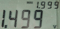
![DSC_4912minmax]() As long as MAXMINAVG is displayed, the display will show the actual value. When only one of the indicators is displayed, it is that value.
As long as MAXMINAVG is displayed, the display will show the actual value. When only one of the indicators is displayed, it is that value.
![DSC_4913minmax]()
![DSC_4922minmax]() Other meters do also use that notation.
Other meters do also use that notation.
![DSC_4919minmax]() This meter is using the secondary display to show minimum and maximum values.
This meter is using the secondary display to show minimum and maximum values.
Peak or fast minimum, maximum
![DSC_4908peak]()
![DSC_4918peak]()
![DSC_4921peak]()
![DSC_4925peak]()
![DSC_4917peak]()
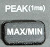
This function can record fast transient, like current while a capacitor charges up (If it is supported in current ranges). It often need around 1ms (0.001s) pulse to record, but it varies with meter. This is fast enough to record maximum and minimum in a mains power sinewave. The function may only be supported in AC modes, but that is no problem because it usual records both maximum and minimum (I have seen exceptions to this). This function will nearly always disable auto ranging, i.e. remember to manually select the correct range.
This function can not replace a min/max, the fast capture means it is much more susceptible to noise and transients.
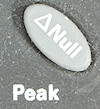
![DSC_4935peak]() A PEAK label is added to the display when recording peak values.
A PEAK label is added to the display when recording peak values.
![DSC_4951peak]() This meter do not have a special peak indicator but uses the Hold indicator together with min/max.
This meter do not have a special peak indicator but uses the Hold indicator together with min/max.
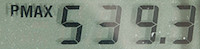
![DSC_4952peak]() Here a P is added before the min/max labels and the value is shown on the secondary display.
Here a P is added before the min/max labels and the value is shown on the secondary display.
![DSC_4953peak]() Brymen uses CREST instead of peak and add a C to min/max.
Brymen uses CREST instead of peak and add a C to min/max.
Freezing the display
![DSC_4900hold]()
![DSC_4902hold]()
![DSC_4903hold]()
![DSC_4904hold]()
![DSC_4907hold]()
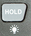
This function freezes the the display, this can be used to move the meter to a better place for reading the value or writing the value down. Just about any meter has this not very useful function.
One press will freeze the display, next press will resume updating again.
![DSC_4920hold]()
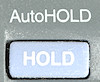
Some meters has a auto-hold or touch-hold or something like that, it will freeze the display when measuring a stable value. This makes it possible to concentrate on the probe and when the meter beeps, remove the probes and read the meter. No button presses is required when doing this.
![DSC_4955hold]()
![DSC_4956hold]()
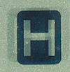
![DSC_4958hold]() Usual one of these 3 indicators are used to show that the display is frozen.
Usual one of these 3 indicators are used to show that the display is frozen.
Manual selecting range
![DSC_4900range]()
![DSC_4902range]()
![DSC_4905range]()
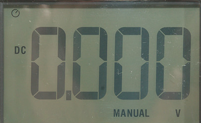
On many auto-ranging multimeters it is also possible to manually select range, sometimes it is even required for a specific ranges (Like mV AC).
MIN/MAX, PEAK and REL will usual select manual ranging, but not on all multimeters. When canceling the function the meter will usual return to automatic ranging again.
Press the button once to lock the current range, press again to step through the different ranges, actual range can usual be seen on the point. Hold the button down to get back to auto-ranging.
This is sometimes used with varing values to avoid the meter changes range all the time. If a lot of resistors or capacitors with about same value has to be checked, manually selecting range will make the meter faster.
![DSC_4911auto]()
![DSC_4914auto]()
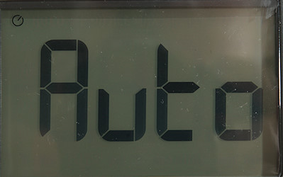
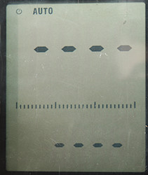
![DSC_4915auto]() Usual there is a AUTO text somewhere on the display when using automatic ranging.
Usual there is a AUTO text somewhere on the display when using automatic ranging.
![DSC_4916auto]()
![DSC_4919auto]() The MANUAL text is not always used.
The MANUAL text is not always used.
Selecting function
![DSC_4900select]()
![DSC_4902select]()
![DSC_4903select]()
![DSC_4904select]()
![DSC_4907select]()
![DSC_4933select]()
![DSC_5036]()
![DSC_5037]()
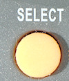
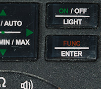
On most multimeters there are more than one function for each rotary switch position, this button is used to select between them or at least some of them.
The color coding of the button often match the some color coding for the markings around the rotary switch.
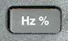
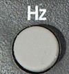
Hz and duty cycle is sometimes select with this button sometimes with a Hz button.
In this document I will call the button SELECT.
![DSC_4900select1]() When the blue switch is pressed the blue function is selected.
When the blue switch is pressed the blue function is selected.
![DSC_4902select1]()
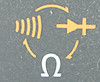
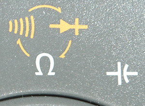
![DSC_4902select2]() Here it is yellow and there are arrows to help with the sequence.
Here it is yellow and there are arrows to help with the sequence.
![DSC_4903select1]()
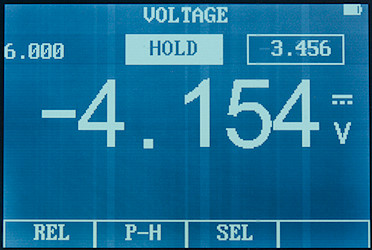
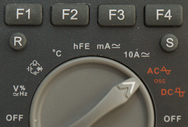
![DSC_4903select2]() Not everybody believes in arrows. This meters starts in AC mode, the = is orange, i.e. SEL must be pressed to select it.
Not everybody believes in arrows. This meters starts in AC mode, the = is orange, i.e. SEL must be pressed to select it.
![DSC_4904select1]()
![DSC_4904select2]() Here it is not possible to see what initial selection is.
Here it is not possible to see what initial selection is.
![DSC_4907select1]()
![DSC_4907select2]() Here it is not even possible to see what the SELECT button do (Southwire had to be different).
Here it is not even possible to see what the SELECT button do (Southwire had to be different).
Each press will move to the next function for that rotary switch position, usual moving the rotary switch or turning the meter off will reset to the initial function again (Brymen and a few other remembers last selection).
Background light and flashlight
![DSC_4902light]()
![DSC_4904light]()
![DSC_4907light]()
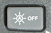
Many multimeters have a light that can illuminate the display, sadly it is often implemented in a way that makes it very awkward to use. On many of the cheaper multimeter it is only on for 15 seconds, then it turns off automatically and it requires a few seconds to turn it on. A few meters uses a light sensor to turn the background light on when it is dark.
The first light button requires a single press to turn the light on, the two next must be held down.
![DSC_4900light]() The background light on this multimeter works different: usual the background will turn on due to a light sensor near the display, i.e. when it is dark around the display the background light turns on. The button disables this function and the background light will stay off, until the meter has been turned off.
The background light on this multimeter works different: usual the background will turn on due to a light sensor near the display, i.e. when it is dark around the display the background light turns on. The button disables this function and the background light will stay off, until the meter has been turned off.
![DSC_4900flight]()
![DSC_4907flight]()
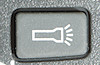
Some lights has a build in flashlight, that may be able to illuminate the place you are measuring (May require an extra person to hold the meter). This flashlight either has its own button or it turns on together with the backlight.
![DSC_5066]()
![DSC_5067]()
![DSC_5068]()
![DSC_5069]()
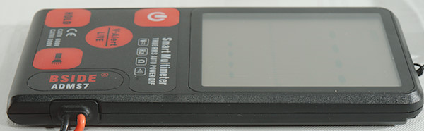
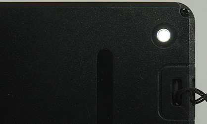
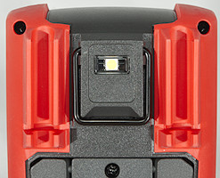
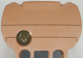
Flashlight placement is either top or back of the multimeter.
Frequency and duty cycle
![DSC_4900hz]()
![DSC_4902hz]()
![DSC_4906hz]()
The SELECT button may select this, but often an extra button is used for selecing frequency and duty cycle measurements.
It varies where this button can be used, but it is in one or more of these ranges:
- V AC – This is nearly always supported.
- V DC
- mV AC – If the meter is missing a Hz mode, this is usual the range with support for the highest frequencies.
- mV DC
- Hz – In the Hz mode it is often the Hz button that select duty cycle, not the SELECT button.
- uA AC
- uA DC
- mA AC
- mA DC
- A AC
- A DC
The meter may or may not support showing frequency for DC pulses (i.e. pulses that do not cross the zero line) and this may not be releated to support for frequency in DC ranges. Adding a capacitor in series with the multimeter or connecting minus on the multimeter to a voltage a bit above ground will make it possible to handle this and measure duty cycle at drive signal levels (0-3V, 0-5V, 0-12V etc.).
Pressing the button will select Hz, next press duty cycle (Not all meters have duty cycle) and third press back to the main function again.
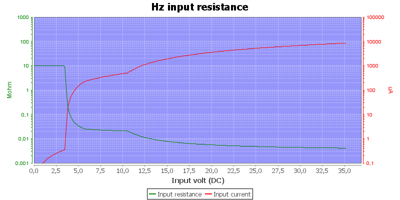
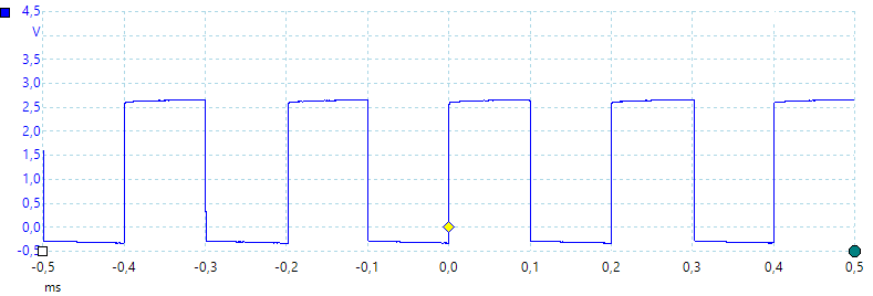
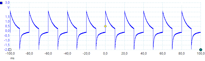
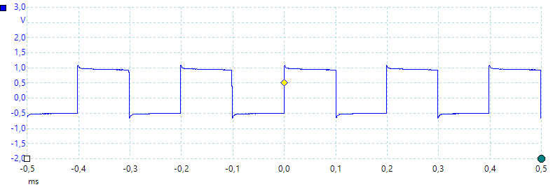
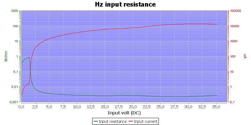
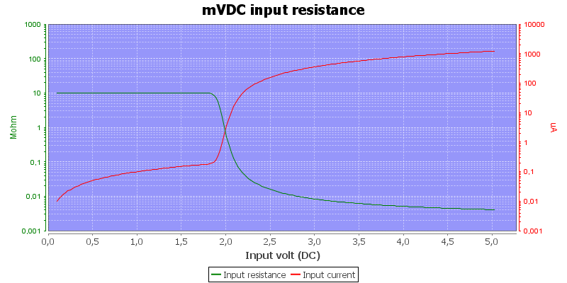
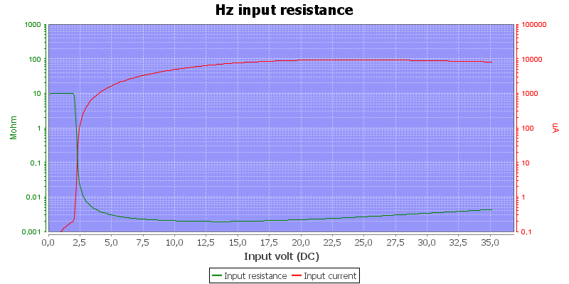
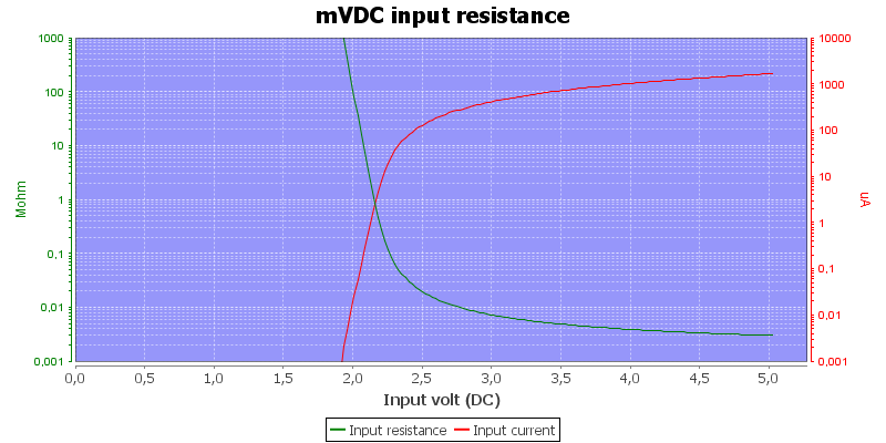
The Hz selection on the rotary switch will usually be designed for low voltage and often support fairly high frequencies (i.e. MHz). The input impedance will often drop to low kOhm above a few volts.
Relative measurements![DSC_4900rel]()
![DSC_4902rel]()
![DSC_4905rel]()
![DSC_4917rel]()
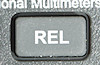
This is a very common function, it is used to “null” out a value and show measurement relative to that. Values to null can be the ohm with shorted probes, but it could also be a unloaded voltage, then the meter will only show the voltage drop when load is applied.
Meters with dual display may show the stored value or the full measured value on one of the displays.
This function will often change to manual ranging on the meter.
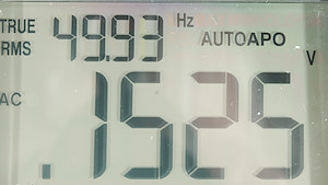
Auto power off, can it be disabled?![DSC_4909apo]()
![DSC_4910apo]()
![DSC_4914apo]()
![DSC_4924apo]()
Nearly all meters will automatic turn power off after some time, sometimes they are smart and disables it when measuring a value or when running max/min function.
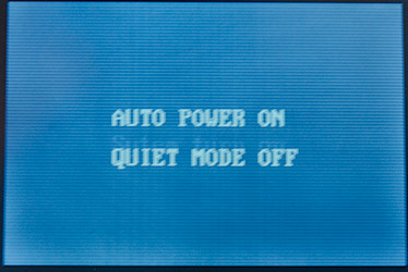
If the meter shows that auto power off is active, it may have a function to disable it. This is usual done by holding one of the buttons down while the meter is turned on (The button must be held down a few seconds). If the symbol is not shown, then the function is disabled.
Dual or triple display![DSC_4938dual]()
Some meters can show more than one value at a time. On some meters you have to use the
SELECT or a special
DUAL button to select reading for the secondary display, but in many cases it is automatic.
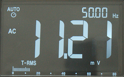
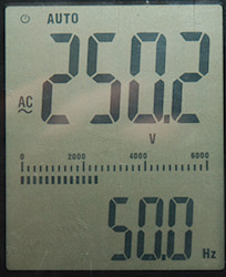
![DSC_4934dual]()
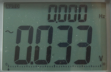
This is the simple dual display, it can only show frequency in AC mode. Some meters only support this!
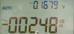
![DSC_4928dual]()
This meter can also show voltage and dB
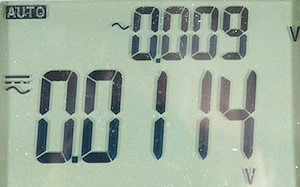
![DSC_4926dual]()
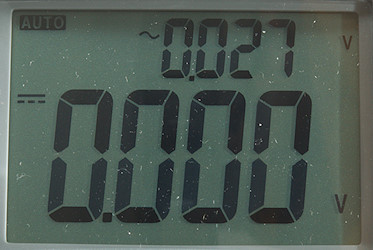
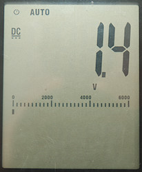
Here is both DC and AC voltage shown at the same time.
![DSC_4930dual]()
Voltage AC and AC+DC, i.e. sqrt(sqr(AC)+sqr(DC))
![DSC_4931dual]()
This triple display is not used for the normal measurements, the two top numbers are always %RH and temperature.
![DSC_4919dual]()
Using the meter in min/max mode is a nice feature, but you have to live with the smaller digits in the secondary display.
![DSC_4936dual]()
This is a advanced multimeter with triple display, here used to measure power while showing both voltage and current.
![DSC_4937dual]()
With min/max it will show the stored value, together with the time. Here the maximum value was a overload.
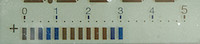
Bargraph, sometimes a fast estimate of value
Meters may have a line at the bottom that shows the value, on better meters this line will update very fast. Some meters cheats with the bargraph and grouped segments, i.e. it looks like it has many segments, but they turned on/off in groups reducing the real resolution.
![DSC_4939bar]()
![DSC_4940bar]()
This bargraph has many segments, i.e. better precision, but it is very close to the bottom of the display, i.e. difficult to see from a low angle.
![DSC_4943bar]()
![DSC_4944bar]()
I am measuring 3V, but the bargraph shows up to 30, this bargraph do not adjust the scale (This is very common).
Voltage measurement
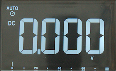
Voltage measurement can cover from one to four or more position on the range switch, it includes the normal voltage measurement, but also some special functions.
- V DC – DC voltage up to maximum voltage supported by the meter, that is usual from 600V to 1000V
- V AC – AC voltage up to maximum voltage supported by the meter, that is usual from 600V to 1000V. This may be lower than DC voltage, due to peak voltage being 1.4 times higher than display reading.
- V AC VFD/LowZ – AC voltage with some special function activated, see below.
- mV DC – DC voltage below 1 volt, sometimes this is a separate range, sometimes it is part of the V DC range.
- mV AC – AC voltage below 1 volt, sometimes this is a separate range, sometimes it is part of the V DC range. When part of V AC it may require manual range selection to select it.
In addition to the standard voltage, it might be possible to select some extra function with
SELECT or
Hz buttons.
- AC+DC – Combined rms voltage for AC and DC
- Frequency – Frequency and duty cycle
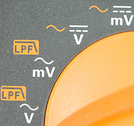
- Low pass filter (LPF) – Low pass filter, used on variable frequency drives (VFD’s) to remove high frequencies.
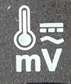
- Temperature – A thermocoupler is very low voltage and the selection may be placed on the mV DC range.
![DSC_4959V]()
This meter have four voltage selections, each with some extra options.
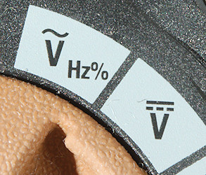
![DSC_4961V]()
Here is only DC/AC and a frequency selection for AC.
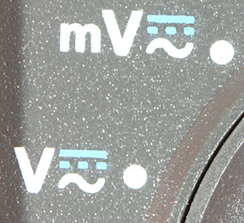
![DSC_4962V]()
This meter has V and mV, AC/DC is done with
SELECT![DSC_4964V]()
3 selections is fairly normal, but here mV is missing AC
![DSC_4966V]()
Only one selection for everything, use
SELECT to change between AC/DC, it may require manual ranging
RANGE to select mV, if the meter supports it. This meter starts in AC (AC symbol is white, DC symbol is orange).
![DSC_4967V]()
3 selections with both AC and DC in the mV range. The temperature selection is also in the mV DC range. Use
SELECT to select between AC/DC and temperature in mV. The
Hz button is used for frequency. Frequency is only supported for AC.
![DSC_4968V]()
Again 3 selection, this time the mV input is also used for frequency and duty cycle, because it often has the highest bandwidth. Use
SELECT to select between AC/DC in mV. The
Hz button is used for frequency.
![DSC_4969V]()
A standard 3 selection meter, use
SELECT to select between AC/DC in mV.
![DSC_4971V]()
The standard 3 selection meter, this meter do not have a
Hz button and all selection are done with
SELECT (That is yellow and unmarked).
Current measurement
A good multimeter has 6 AC/DC current ranges, two uA, two mA and two A. This usual requires two or 3 positions on the range switch (mA uA requires a switch, A uses another terminal and do not need a extra switch position). Good meters will also have some way to warn the users if they select voltage with probes connected to some current range, to avoid a blown fuse.
Just because the meter has a A on the range switch do not means it has two A ranges, some meters only has the 10A/20A range, not the xA range.
![DSC_4961A]()
The typically 3 positions, use
SELECT to change between AC/DC.
![DSC_4964A]()
Again 3 positions, use
SELECT to change between AC/DC.
![DSC_4972A]()
This meter do not have the two uA ranges, use
SELECT to change between AC/DC and frequency (This meter do not have a
Hz button).
![DSC_4973A]()
On this meter uA and mA is on the same position, this must mean it has electronic selection between them (Not very common). Use
SELECT to change between AC/DC.
![DSC_4974A]()
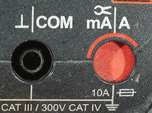
mA and A is combined and the meter uses the input terminal to select the correct range. Use
SELECT to change between AC/DC, frequency and percent of 4-20mA (Standard for industrial sensors).
![DSC_4975A]()
This meter is missing the mA range.
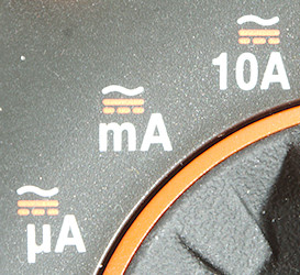
![DSC_4977A]()
A standard 3 selection meter, the 10A marking probably means it is missing the low A range.
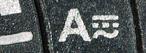
![DSC_4978A]()
A one selection meter, this does not mean it is missing uA and mA, this meter can electronically select from uA over mA to 10A.
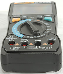
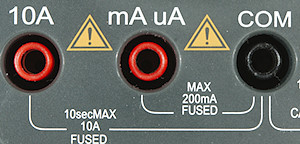
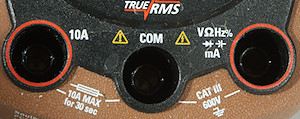
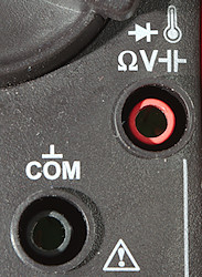
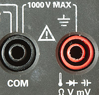
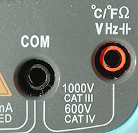
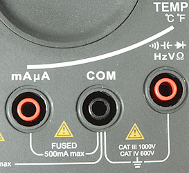
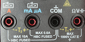
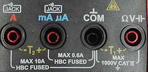
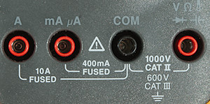
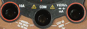
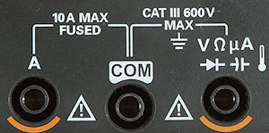
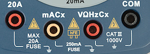
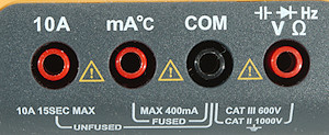
Lets also take a look at the input terminals for current. Usual there is on for A and one for uA and mA, but a few meters move the uA and mA to the voltage input, this can be problematic due to the increased risk of measuring volt on a current range.
![DSC_4980A]()
A classical current input layout with one A socket and one uA mA socket.
![DSC_4982A]()
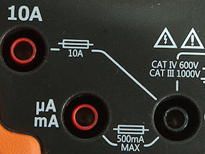
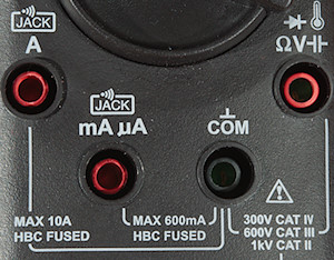
The terminals are not always on a line, but it is the standard layout.
![DSC_4983A]()
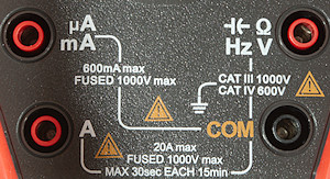
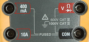
Even in a square.
![DSC_4985A]()
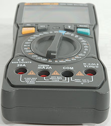
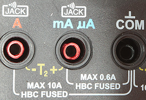
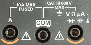
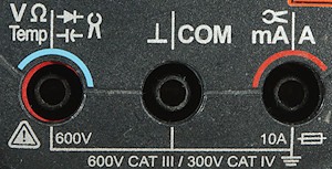
In a row and this meter can warn about probes in the wrong terminals.
![DSC_4981A]()
Here is a more problematic layout, uA and mA is on the volt input, this increases the risk of blowing a fuse.
![DSC_4976A]()
On this meter uA is on the volt input and has electronic protection, i.e. no blow fuse if mains voltage is connected to the uA range.
![DSC_4984A]()
On this meter it is not even possible to have a probe in the A input when selecting a voltage range. The same terminal is used for uA, mA and A (This meter uses electronic selection).
Ohm, continuity, diode and capacity measurement
These four function has one thing in common: The meter must supply some current to do the measurement.
This can be up to about 3V and 2mA, but will often be considerable lower, depending on function. Bench meters may use up to 10V and a single multimeter has a 15V diode mode.
- Ohm – Measuring resistance, lowest range may have a resolution from 1ohm down to 0.001ohm (1mOhm), depending on meter, highest range usual goes into the Megaohm, sometimes up to more than 50Mohm. A few meters support up to Gohm, but that is usual measured as ns (nano siemens: 1000000000/ohm).
- Continuity – Audible resistance check, this range uses one of the low ohm ranges (Not always the lowest and test current/voltage may be slightly different) and will sound a buzzer when the resistance is low (Often below 50ohm, but varies with meter and may even be selectable). In addition to the buzzer some meters may also flash a light when continuity is detected.
This is useful to trace wires, because you do not have to check the display, but can use the sound and a good continuity mode is very fast. This means you can pull the probe across a couple of connection and the beep will sound when you hit one with a matching connection.
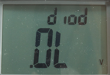
- Diode – Test forward voltage of a diode, some meters uses up to 3 volt and can test white leds, others only use 1 volt and cannot test any leds only regular diodes. If working with white leds a meter that can show 3V in diode mode is very useful.
- Capacity – Measure capacitors, but the low and high end varies significantly depending on meter.
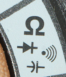
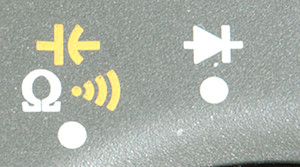
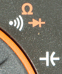
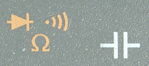
- ohm
![DSC_4989ohm]()
![DSC_4994ohm]()
![DSC_4995ohm]()
The nS is a special ohm mode that measures 1000000000/ohm and can be used for very high resistance.
- Continuity
![DSC_4986ohm]()
![DSC_4990ohm]()
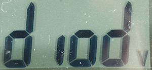
- Diode
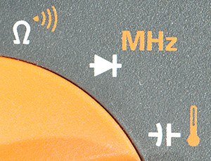
![DSC_4988ohm]()
![DSC_4991ohm]()
![DSC_4992ohm]()
It looks like somebody forgot the diode symbol for the second one.
- Capacity
![DSC_4987ohm]()
![DSC_4993ohm]()
It will be nano (n), micro (u) and sometimes milli (m) farad that is shown as unit.
![DSC_4959ohm]()
This meter uses 3 selections and can obvious disable current generation electronically and use the ranges for other purpose also.
![DSC_4961ohm]()
Here all the ranges are collection in one position and
SELECT must be used to select the desired one.
![DSC_4962ohm]()
Again 3 selection, but no alternate functions.
![DSC_4964ohm]()
Two selections.
![DSC_4966ohm]()
Two selections.
![DSC_4967ohm]()
One selection.
![DSC_4968ohm]()
Two selections.
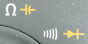
![DSC_4969ohm]()
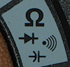
Two selection, this time with a nicely marked sequency for ohm->continuity->diode.
![DSC_4971ohm]()
Two selection.
Temperature measurement![DSC_5006]()
![DSC_5008]()
![DSC_5010]()
![DSC_5012]()
![DSC_5014]()
![DSC_5016]()
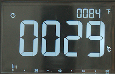
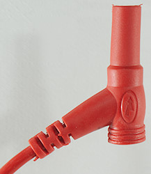
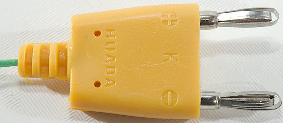
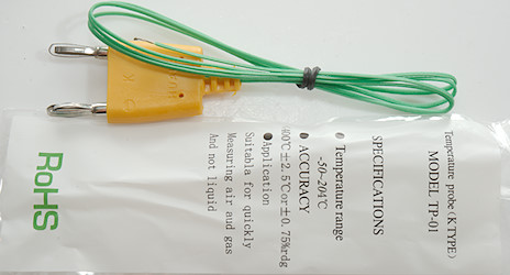
Many multimeters can use an external temperature sensor called a thermocoupler. This is a very simple temperature sensor that can cover a wide temperature range, but has a fairly low signal level.
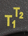
A few meters can handle two thermocouplers at the same time and may be able to show the difference between them, this can be very useful when working with ventilations and airconditions systems.
The thermocoupler is fairly linear for temperature above about -40°C, for this reason many meter either has a lower limit around this or shows large errors at lower temperatures. There is also meters that has compensation and will show correct at lower temperatures.
![DSC_5007]()
Usual a single thermocoupler is connected to the volt input terminal.
![DSC_5013]()
Volt input
![DSC_5015]()
And volt input.
![DSC_5017]()
But somebody always has to be different, here it is the mA input.
![DSC_5011]()
With two sensors it is the volt and mA input, because they are both handled by the range switch.
![DSC_5009]()
To get four terminals, the A input is basically connected to
COM at low currents (0.01ohm resistor and fuse) and can also be used for a second thermocoupler ground.
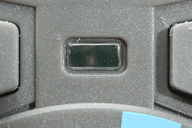
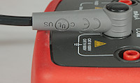
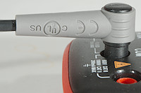
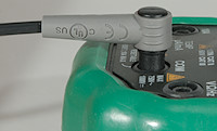
Non contact voltage or electric field detection![DSC_5020]()
![DSC_5023]()
![DSC_5018]()
![DSC_5019]()
![DSC_5026]()
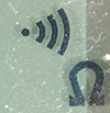
This function can be used to check for mains voltage without using probes, just by holding the meter near to the wires, at least in theory. The sensitivity depends on how you hold the meter and a wet surface or wire will block for this function.
Often both buzzer and a led will be used to notify about a electric field in addition to the display.
The function can be useful for checking what wire is live or in some cases tracking a live wire, just never assume that everything is safe, just because the
NCV do not show anything.
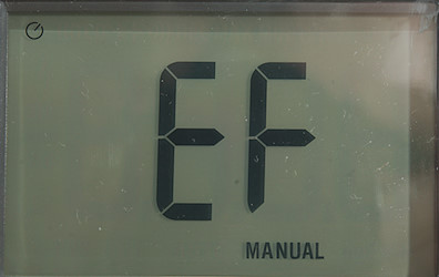
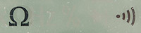
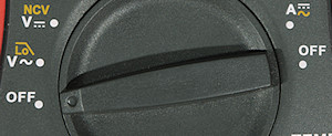
The function is usual called
NCV and shown as EF on the display, but as can be seen above the selector can also be named EF or even Vsense.
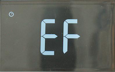
![DSC_5021]()
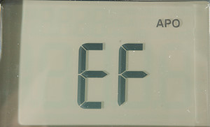
Many meters use the letters EF (
Electric
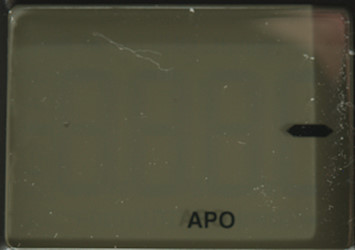
Field) in the display when range is select and no field is detected.
![DSC_5022]()
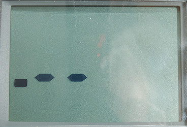
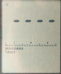
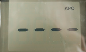
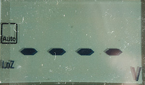
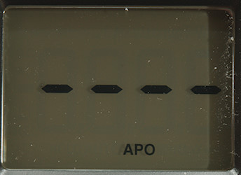
Indication is usually with 1 to 4 bars on the display, depending on the strength of the electric field.
![DSC_5028]()
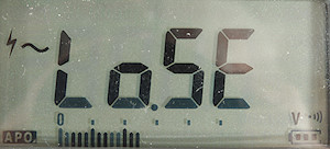
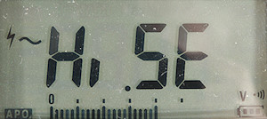
This meter uses LoSE for low sensitivity and shows the detected field strength on the bargraph.
![DSC_5029]()
A press on the
RANGE button and the text is HiSE for High sensitivity.
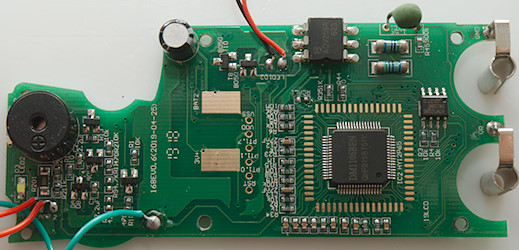
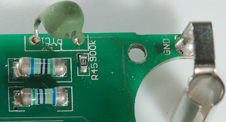
Low-Z, getting rid of ghost voltages![DSC_4996]()
![DSC_5000]()
![DSC_5003]()
![DSC_5004]()
![DSC_5005]()
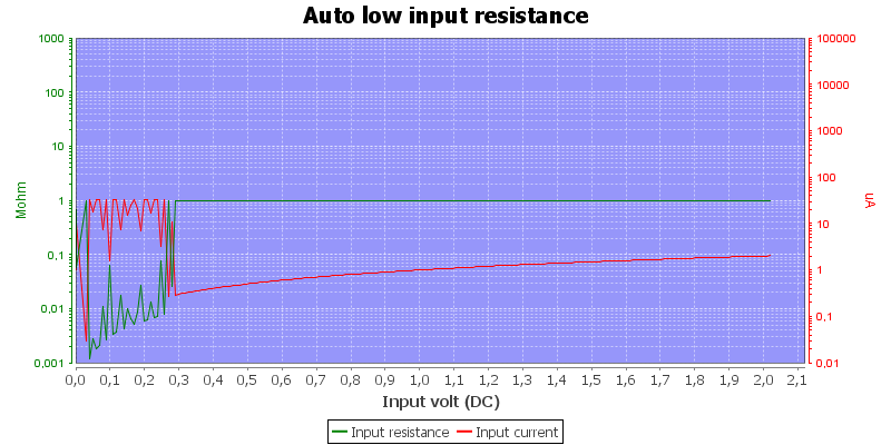
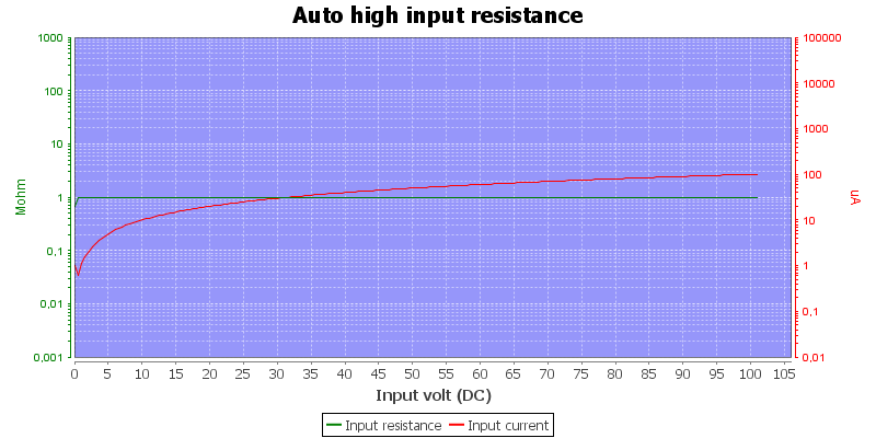
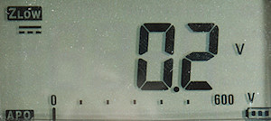
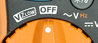
This function is mostly for mains work. Due to the high input impedance (10Mohm) of multimeters two mains wires in a cable or in a pipe will both show voltage when one has voltage and the other is unconnected. This is because there is some capacity between the wires and a small current will leak. Using the Low-Z mode on a meter will put enough load on the wire to show these leaks as safe voltages, but any real voltage (I.e. with enough current to drive loads) will still be measureable.
This function will usual switch the meter to the highest voltage range and sometimes to AC mode. It is often implemented as a
PTC, that may be down to about 2kOhm when cold and will increase to maybe 100kOhm very fast when mains voltage is applied. This function may not work with low voltages.
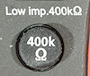
The 400kOhm is slightly different, it simply connect a resistor across the voltage input when held down and do not care about what range is selected.
Most of the time the display will be in V AC mode, but here are a few exceptions:
![DSC_5001]()
This meter will automatically detect AC/DC voltage.
![DSC_5002]()
Another Low-Z mode that will handle both AC and DC.
Low pass filter for variable frequency drives![DSC_5030]()
![DSC_5031]()
![DSC_5034]()
![DSC_5038]()
When measuring on motor drives, also called variable frequency drives (
VFD) the voltage will contain many harmonic frequencies. To avoid they skew the measurement some meters has a function to filter higher frequencies out. This is usual only required on high end meters, other meters do not have enough bandwidth in the first place, i.e. there is a low pass filter always active.
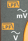
The function is usual activated with the
SELECT button and will show a small icon in the display:
![DSC_5032]()
![DSC_5033]()
![DSC_5035]()
![DSC_5039]() Turning the meter on or off
Turning the meter on or off
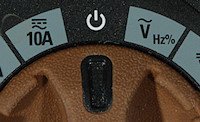
All meters needs a power switch, usual it is on the range switch, but a few meters use a button, usual an electronic switch. Neither soft buttons or auto power off will usual not turn the meter fully off, but the current may be negligible.
![DSC_5108]()
![DSC_5109]()
![DSC_5110]()
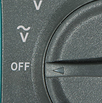
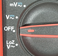
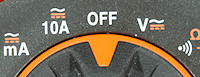
The most common off location is with the rotary switch all the way to the left.
![DSC_5107]()
![DSC_5103]()
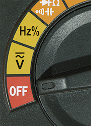
If the meters has a Low-Z mode it will often be placed below the off position, this makes it fast to select this position when turning the meter on.
![DSC_5106]()
Some meters has a off at both ends of the range switch, this can reduce the wear on the range switch if the meter is mostly used for current.
![DSC_5104]()
![DSC_5112]()
Another way to do that is to place off at the center of the range switch. This will also mean less turning of the switch to select range.
![DSC_5105]()
![DSC_5111]()
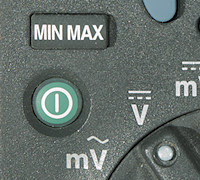
A few meters use a button to turn on off, for better meters it is a electronic switch.
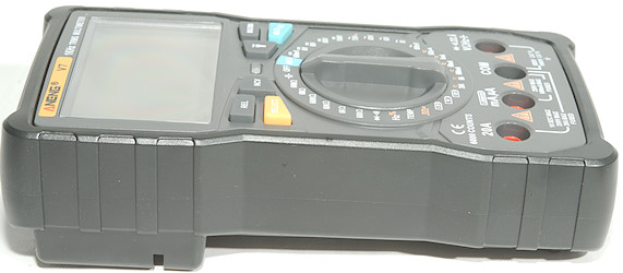
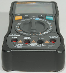
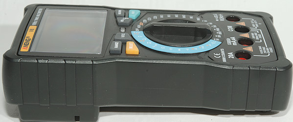
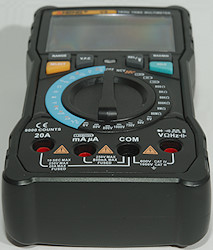
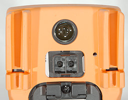
Input terminals![DSC_5041]()
![DSC_5040]()
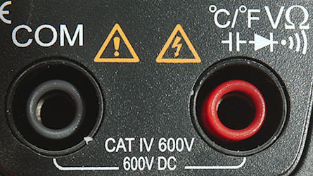
Usual multimeters have the terminals placed in a standard way, like shown above, but there are exceptions.
![DSC_5042]()
![DSC_5043]()
They do not need to be on a line.
![DSC_5046]()
Some multimeters can electronically switch current ranges from uA to A and only need one current terminal. The voltage and current inputs are also swapped on this meter.
![DSC_5044]()
![DSC_5045]()
Then there are meters with less current ranges.
![DSC_5047]()
Here the common and voltage input are swapped and the capacity terminals are mA and V input.
![DSC_5048]()
This looks standard, but the distance between
COM and voltage input is not 19mm, but smaller. This means modules to plug into multimeters will not fit.
![DSC_5051]()
There is also a point about how well standard probes fits into the terminals. The above picture shows a fully inserted probe.
![DSC_5050]()
On this small multimeter the sockets are not deep enough to fully insert the standard probe.
The probes supplied with the meter will go fully into the socket.
![DSC_5052]()
On this multimeter there is some probe detection that prevents fully inserting the standard probe.
The probes supplied with the meter will go fully into the socket.
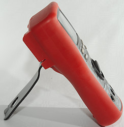
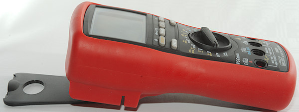
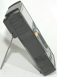
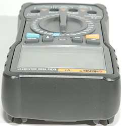
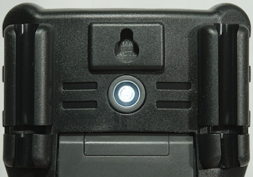
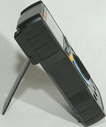
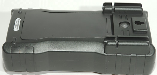
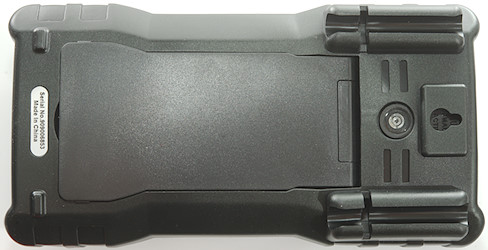
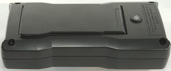
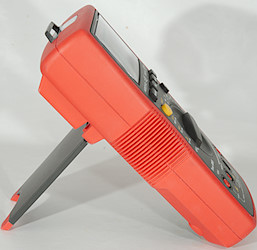
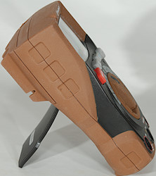
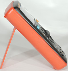
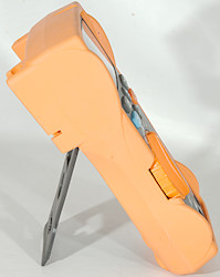
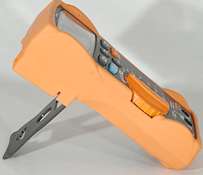
Tilting bale or kickstand![DSC_5054]()
![DSC_5070]()
![DSC_5072]()
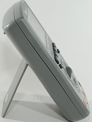
Sometimes it is nice to get a bit of angle on the multimeter, instead of having it lying flat.
![DSC_5053]()
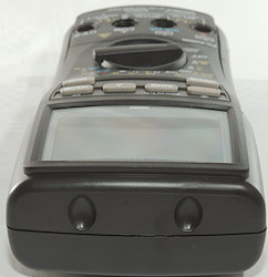
Most meters have a tilting bale or kickstand on the back, this one with rubber tips, that makes the meter more stable when using it.
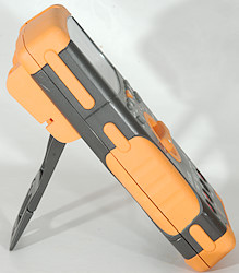
![DSC_5055]()
![DSC_5056]()
![DSC_5057]()
Some meters have more positions for the kickstand, making it possible to select the best angle or even use it to hang the meter somewhere.
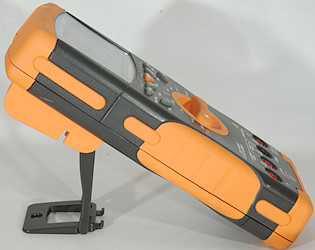
![DSC_5058]()
![DSC_5059]()
Another way to make more angles possible.
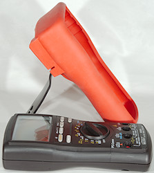
![DSC_5061]()
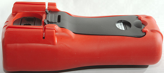
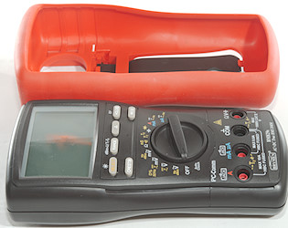
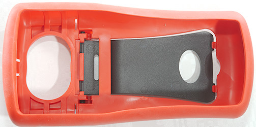
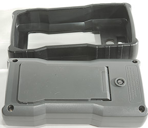
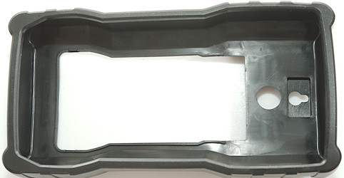
The kickstand can be part of the multimeter or part of the cover.
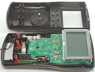
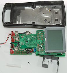
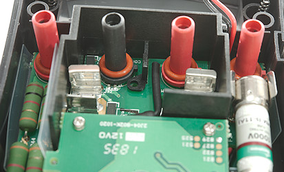
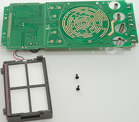
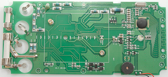
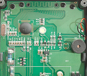
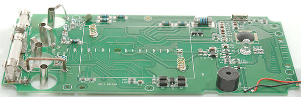
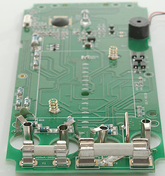
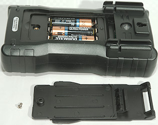
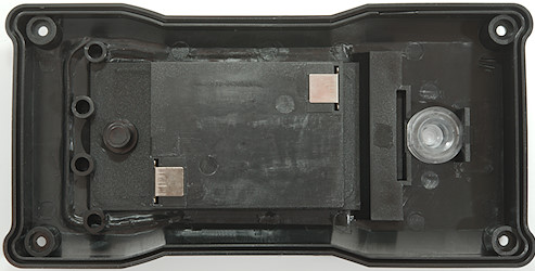
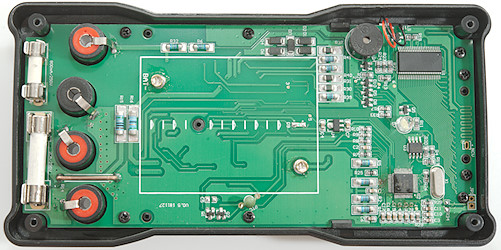
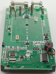
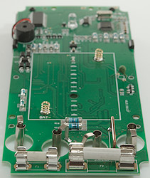
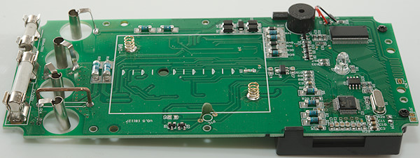
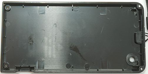
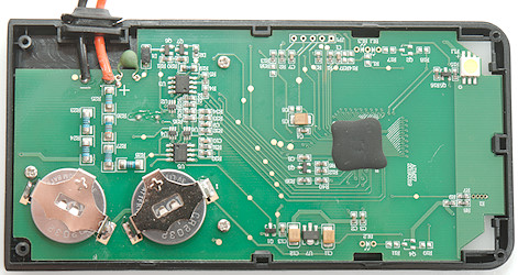
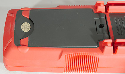
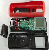
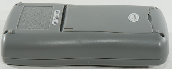
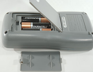
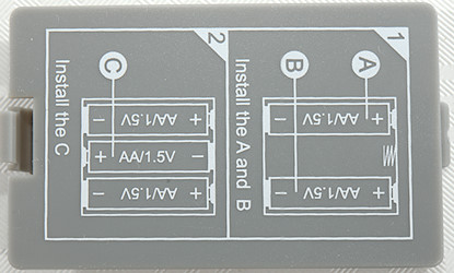
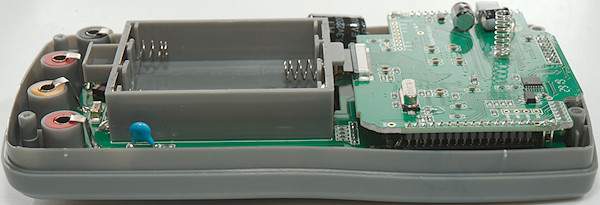
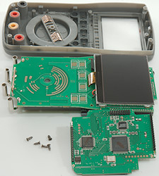
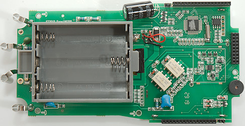
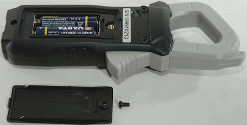
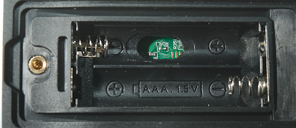
Batteries and fuses![DSC_5088]()
![DSC_5083]()
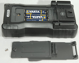
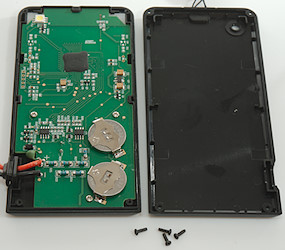
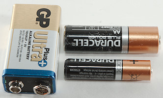
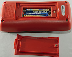
All multimeters needs batteries and most also needs fuses. The batteries are usual 9V, AA or
AAA batteries, for very small meters coin or button cells may be used. A single 9V or from two to 6 AA/AAA batteries, battery lifetime is from below 100 hours to above 1000 hours depending on the meter and battery.
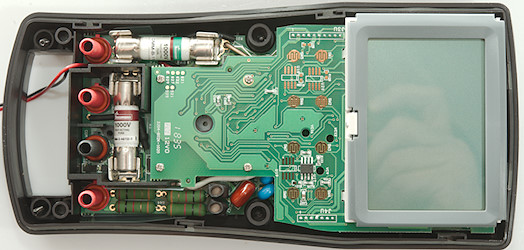
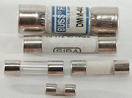
The fuses need for high current and voltage are
HRC (High Rupture Capacity) fuses that can break many thousand ampere. These fuses are ceramic (or better) and is filled with sand. The large DMM44 fuse is of that type.
The glas fuse and small ceramic fuse can probably handle normal mains voltage after a breaker or fuse and are basically for hobby meters.
And then there are the fuses in between, ceramic and hopefully filled with sand.
It is always a good idea to check if the fuses are rated for at least the same voltage as the meter, they must be able to break the circuit if you put the probes in ampere and starts measuring volt. This is the worst case scenario and can be fatal if the fuse cannot break the current in a high current situation.
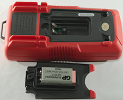
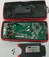
![DSC_5087]()
![DSC_5086]()
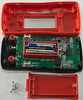
A typical meter, one screw and there is battery access, but two more screws must be removed before there is access to the fuses.
![DSC_5085]()
![DSC_5082]()
One more with this two level access.
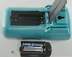
![DSC_5077]()
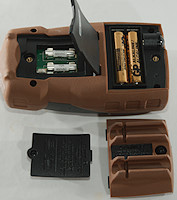
This one is smarter, here is two different lids, one for batteries and one for fuses.
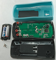
![DSC_5078]()
![DSC_5079]()
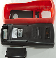
This meter is a bit difficult, before the battery can be replaced the cover must be removed and again the meter must be opened to replace fuses.
![DSC_5080]()
![DSC_5081]()
Here the battery is easy to replace, but for fuses the rubber cover must be removed and the meter opened.
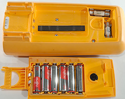
![DSC_5073]()
![DSC_5076]()
Fluke is using a single screw that must only be turned half a turn with a coin and there is access to both batteries and fuses. This meter is a high end meter that uses a lot of power.
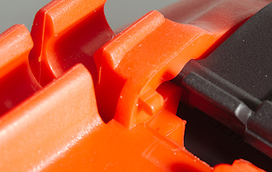
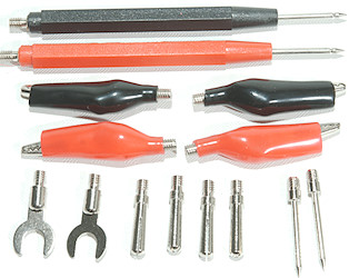
Probe holders, need an extra hand
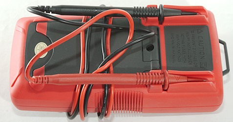
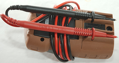
Many multimeters have probe holders build into the body, they can be used when storing the meter in a toolbag, but also when using the meter.
![DSC_5096]()
I have never found a good way to pack the wires.
![DSC_5099]()
![DSC_5101]()
Need to hold two probes and a multimeter, easy with one of the probe holders.
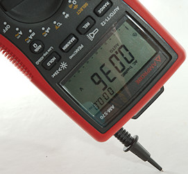
![DSC_5102]()
Sometimes you can be lucky and probe wire length match exactly with the probes in the holders.
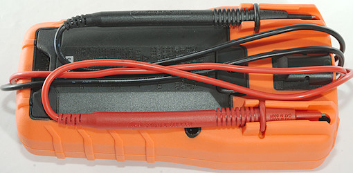
![DSC_5091]()
This meter is too short the sharp end of the probe is poking out.
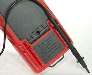
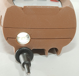
![DSC_5093]()
![DSC_5095]()
But the flashlight is very useful in dark places and aimed the same was as a probe in the holder.
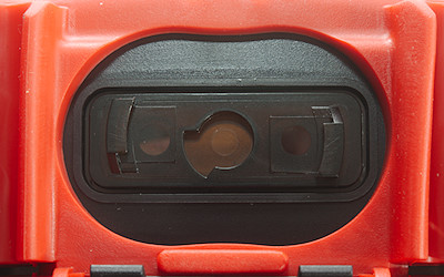
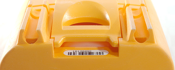
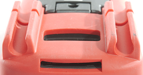
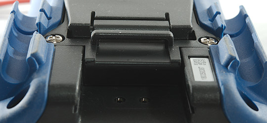
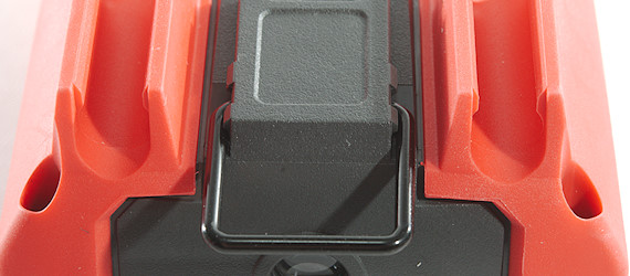
Hanger
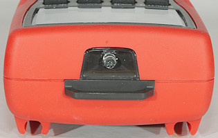
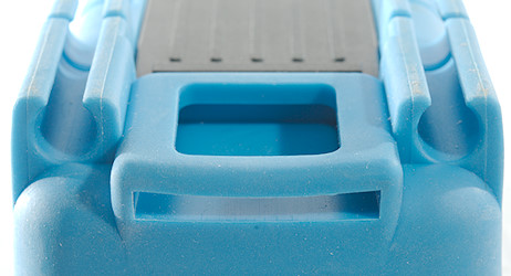
Many meters has a way to hang them, either from a hook/nail/screw or on some metal.
![DSC_6477]()
![DSC_6478]()
![DSC_6479]()
![DSC_6481]()
![DSC_6480]()
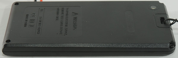
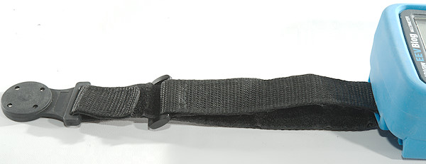
A lot of meters has this kind of holes on the back, it somtimes be used to hand the meter on a hook/nail/screw, but it can also be used with a magnetic hanger.
![DSC_6482]()
This strap is a magnetic hanger, at one end is a powerful magnet with plastic coating.
Sometimes meters will not fit a standard strap, but only a brand specific magnetic hanger.
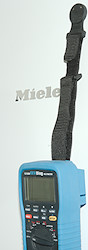
![DSC_6483]()
Here I have mounted it on a multimeter
![DSC_6484]()
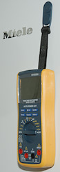
![DSC_6166]()
And the meter can hang on my fridge, metal shelves, electric distribution board in metal, machines. The other meter included the magnetic hanger.
I have also seen a few meters with a magnet build into the back of the meter.
Other articles about multimetersMultimeter and component testingMultimeter probesMultimeter and voltage measurementsMultimeter and pulsed DC current (PWM)Tolerance specifications for multimetersClamp meters magnetization, demagnetization and offsetMultimeters and current measurementsMultimeters and thermocouplesMultimeter designMultimeter protection and safetyMultimeter reviewsMultimeter selection table 


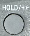
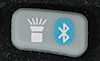
 : Press to freeze/unfreeze current reading, hold down to turn on background light,
  : Press to use relative mode (REL), hold down to enable/disable Bluetooth.
 : Resistance, continuity and diode
 : Capacitance


 : Shows values relative to current value.
  : Resistance and continuity, the nS makes it possible to measure very huge resistance
  : Capacitance and diode range.
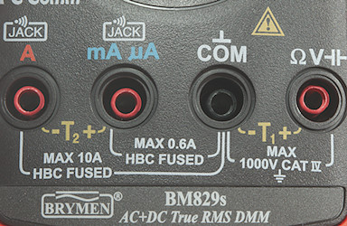


 : Turns the flashlight on.
 : 12V Battery test
 : 9V Battery test
 : 1.5V Battery test
 : Frequency output from 50Hz to 5000Hz, use
  : Continuity and diode mode, there is no selection, it is a single mode that do both and for a combined mode it works fairly well.
 : Capacity
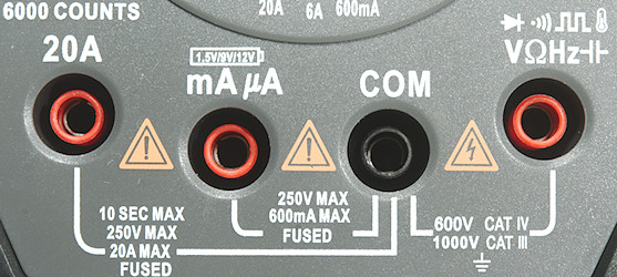

 : Frequency output from 50Hz to 5000Hz, use
  : 12V battery test
 : 9V battery test
 : 1.5V battery test.
 : Continuity
 : Diode
 : Capacitance
 : Resistance
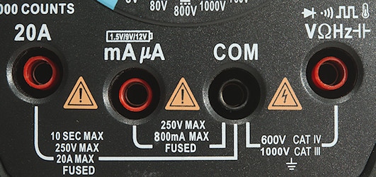

 : A press on this button will turn the meter on or off. Both on and off only requires a short press.
 : A short press will turn on the flashlight.


 : Turn backlight on, hold down to change dual display mode. When showing duty-cycle or pulse time it will change polarity.
 : Resistance and continuity, use
  : Diode and frequency, use
  : Capacitance and temperature.
 : Frequency out mode.


 As long as
 Other meters do also use that notation.
 This meter is using the secondary display to show minimum and maximum values.


 A
A  This meter do not have a special peak indicator but uses the Hold indicator together with min/max.
 Here a P is added before the min/max labels and the value is shown on the secondary display.
 Brymen uses


 Usual one of these 3 indicators are used to show that the display is frozen.


 Usual there is a
 The
The 


 When the blue switch is pressed the blue function is selected.
 Here it is yellow and there are arrows to help with the sequence.
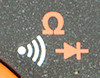
 Not everybody believes in arrows. This meters starts in AC mode, the = is orange, i.e.
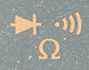
 Here it is not possible to see what initial selection is.
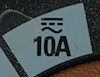
 Here it is not even possible to see what the
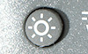

 The background light on this multimeter works different: usual the background will turn on due to a light sensor near the display, i.e. when it is dark around the display the background light turns on. The button disables this function and the background light will stay off, until the meter has been turned off.


 This is the simple dual display, it can only show frequency in AC mode. Some meters only support this!
 This meter can also show voltage and dB
 Here is both DC and AC voltage shown at the same time.
 Voltage AC and AC+DC, i.e. sqrt(sqr(AC)+sqr(DC))
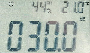 This triple display is not used for the normal measurements, the two top numbers are always %RH and temperature.
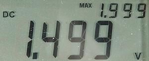 Using the meter in min/max mode is a nice feature, but you have to live with the smaller digits in the secondary display.
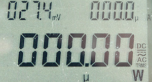 This is a advanced multimeter with triple display, here used to measure power while showing both voltage and current.
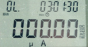 With min/max it will show the stored value, together with the time. Here the maximum value was a overload.
 This bargraph has many segments, i.e. better precision, but it is very close to the bottom of the display, i.e. difficult to see from a low angle.
 I am measuring 3V, but the bargraph shows up to 30, this bargraph do not adjust the scale (This is very common).
 This meter have four voltage selections, each with some extra options.
 Here is only DC/AC and a frequency selection for AC.
 This meter has V and mV, AC/DC is done with
 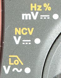 3 selections is fairly normal, but here mV is missing AC
 Only one selection for everything, use
 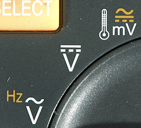 3 selections with both AC and DC in the mV range. The temperature selection is also in the mV DC range. Use
 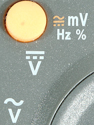 Again 3 selection, this time the mV input is also used for frequency and duty cycle, because it often has the highest bandwidth. Use
 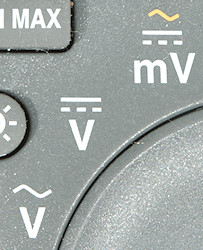 A standard 3 selection meter, use
 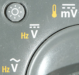 The standard 3 selection meter, this meter do not have a Hz button and all selection are done with
 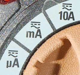 The typically 3 positions, use
 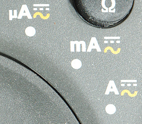 Again 3 positions, use
 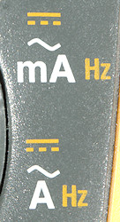 This meter do not have the two uA ranges, use
 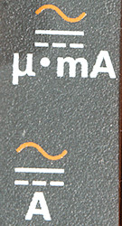 On this meter uA and mA is on the same position, this must mean it has electronic selection between them (Not very common). Use
 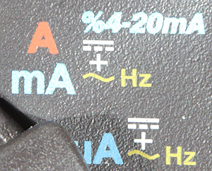 mA and A is combined and the meter uses the input terminal to select the correct range. Use
 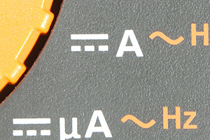 This meter is missing the mA range.
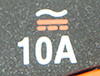
 A standard 3 selection meter, the 10A marking probably means it is missing the low A range.
 A one selection meter, this does not mean it is missing uA and mA, this meter can electronically select from uA over mA to 10A.
 A classical current input layout with one A socket and one uA mA socket.
 The terminals are not always on a line, but it is the standard layout.
 Even in a square.
 In a row and this meter can warn about probes in the wrong terminals.
 Here is a more problematic layout, uA and mA is on the volt input, this increases the risk of blowing a fuse.
 On this meter uA is on the volt input and has electronic protection, i.e. no blow fuse if mains voltage is connected to the uA range.
 On this meter it is not even possible to have a probe in the A input when selecting a voltage range. The same terminal is used for uA, mA and A (This meter uses electronic selection).


 This meter uses 3 selections and can obvious disable current generation electronically and use the ranges for other purpose also.
 Here all the ranges are collection in one position and
 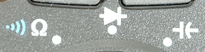 Again 3 selection, but no alternate functions.
 Two selections.
 Two selections.
 One selection.
 Two selections.
 Two selection, this time with a nicely marked sequency for ohm->continuity->diode.
 Two selection.

 Usual a single thermocoupler is connected to the volt input terminal.
 Volt input
 And volt input.
 But somebody always has to be different, here it is the mA input.
 With two sensors it is the volt and mA input, because they are both handled by the range switch.
 To get four terminals, the A input is basically connected to


 Many meters use the letters EF (Electric Field) in the display when range is select and no field is detected.
 Indication is usually with 1 to 4 bars on the display, depending on the strength of the electric field.
 This meter uses LoSE for low sensitivity and shows the detected field strength on the bargraph.
 A press on the
 This meter will automatically detect AC/DC voltage.
 Another Low-Z mode that will handle both AC and DC.


 : ohm, diode, continuity and capacity, use F3/SEL to select.
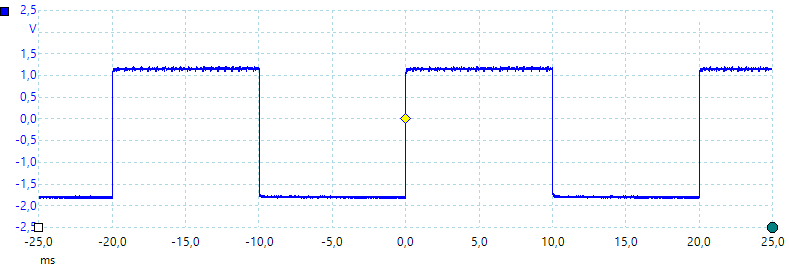
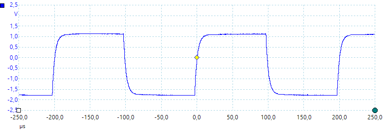
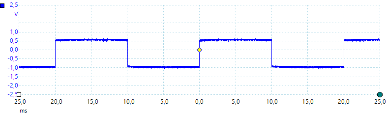
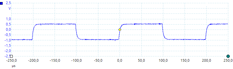
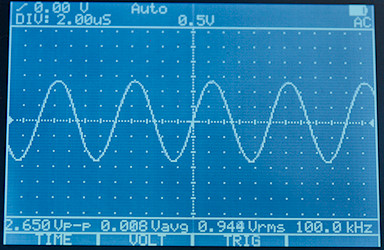
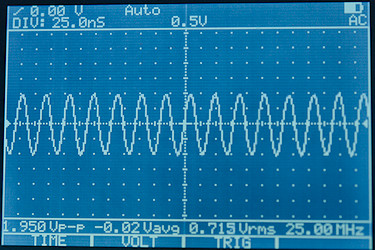
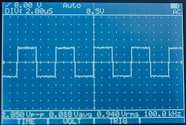
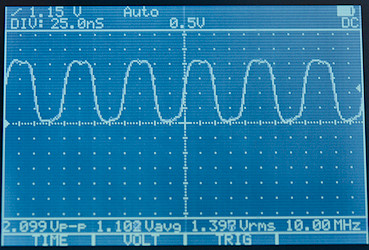
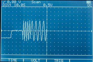
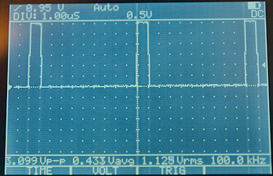
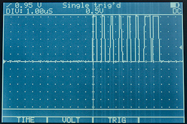
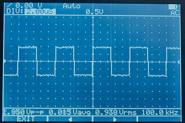
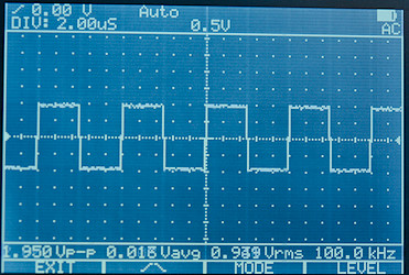
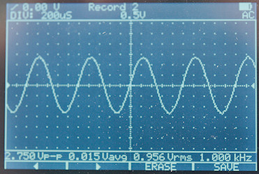
 : Oscilloscope mode with AC input
 : Oscilloscope mode with DC input
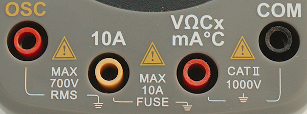
 z
z


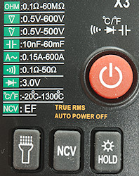
 : Change mode: Auto/VDC/VAC/Continuity/Diode/Capacity/Celsius/Fahrenheit, hold down to turn on off.
 : Turn flashlight on/off.