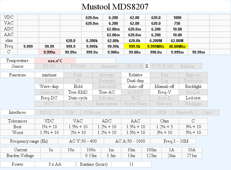
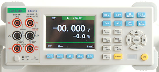
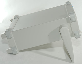
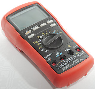
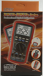
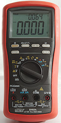
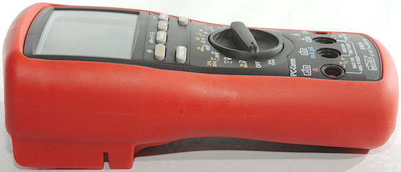
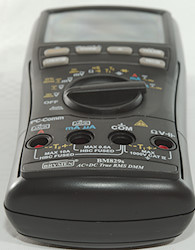
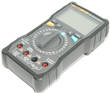
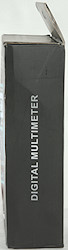
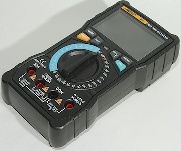
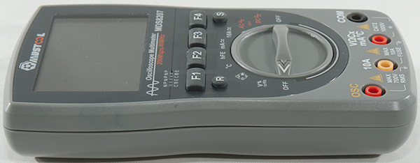
DMM Keysight U1282A
![DSC_7583]()
Keysight is on of the very large test and measure manufacturers, with anything from simple DMM to highly advanced and expensive measure equipment. This meter is one of their most advanced DMM’s. This series has two meters: U1281A & U1282A, the 81 has less bandwidth and are missing some functions.
Contents
Display
Functions
Input
Measurements
Configuration
Software on PC (Handheld Meter Logger Software)
Software on Android (Mobile Meter)
Software on Android (Meter Logger)
Tear down
Conclusion
Notes
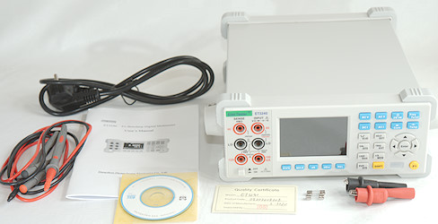
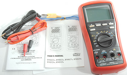
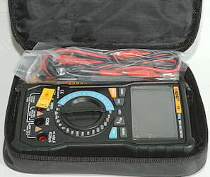
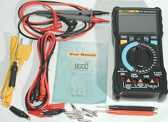
This is one of my own meters, i.e. I bought it a couple of years ago to use it, not review it. This means I have no photos of box or accessories.
Before the review I updated the firmware to the latest version.
![DSC_7591]()
![DSC_7597]()
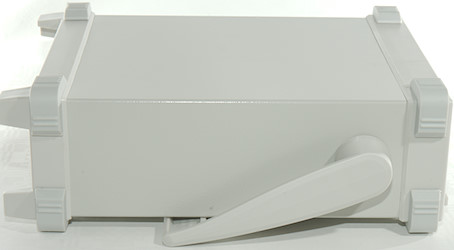
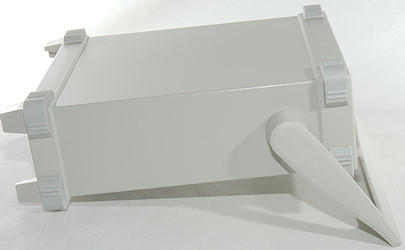
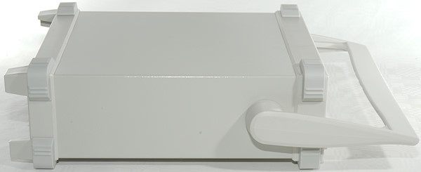
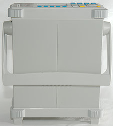
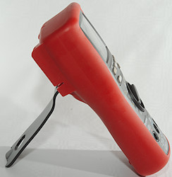
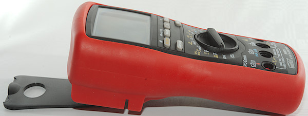
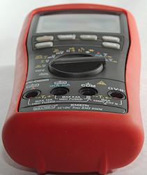
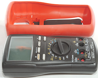
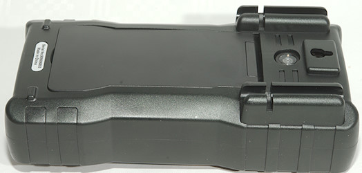
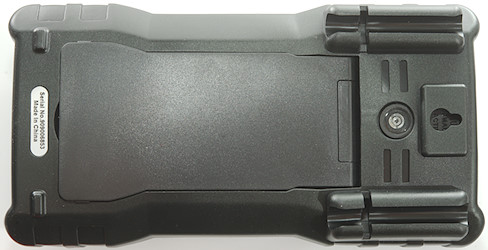
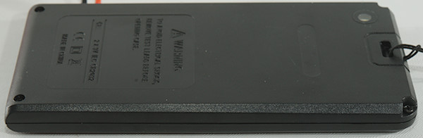
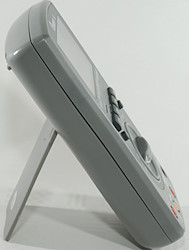
The meter is heavy and the tilting bale can hold it while the range switch is used or the buttons is pressed.
![DSC_7588]()
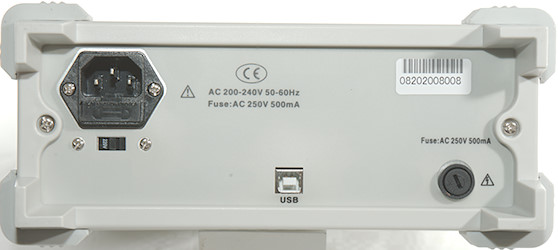
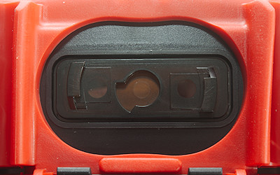
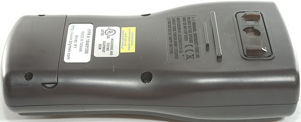
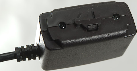
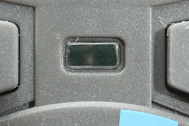
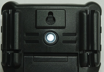
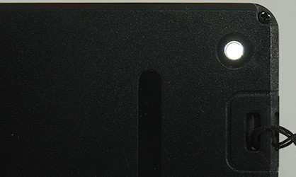
The PC connection is here with an optical link. The cable was included with the meter.
![DSC_7584]()
![DSC_7585]()
![DSC_7586]()
![DSC_7587]()
![DSC_7618]()
![DSC_7619]()
![DSC_7620]()
![DSC_7621]()
![DSC_7622]()
![DSC_7623]()
![DSC_7624]()
![DSC_7626]()
The two fuses.
![DSC_7627]()
![DSC_7628]()
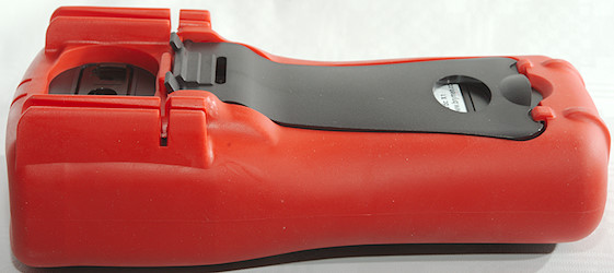
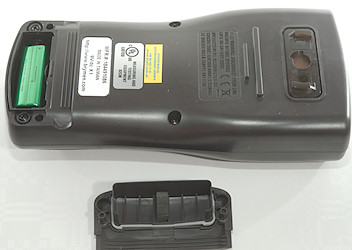
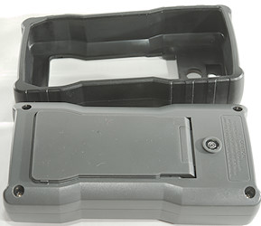
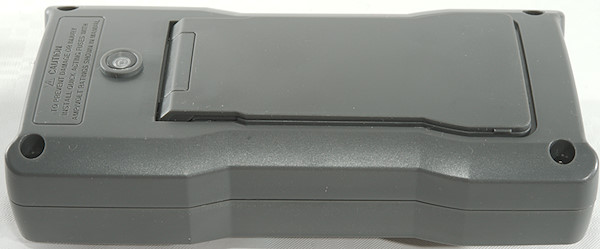
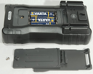
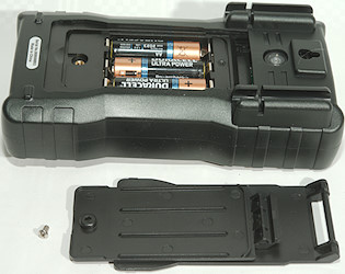
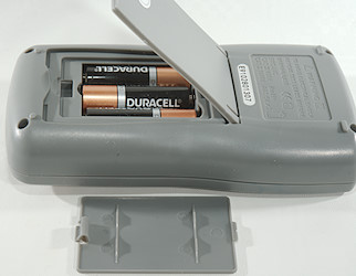
The rubber seal must be pulled up to replace the batteries.
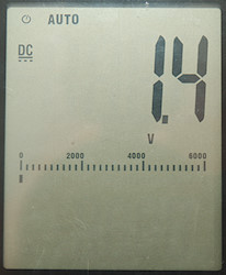
Display
![DSC_7606]()
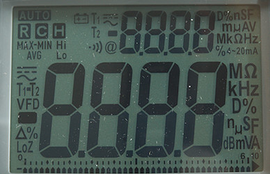
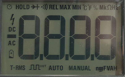
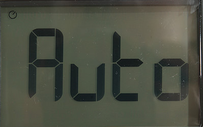
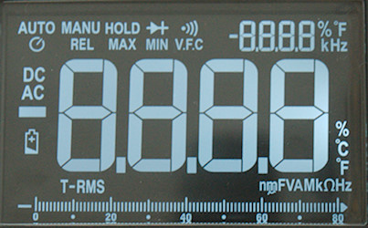
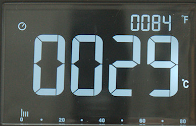
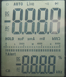
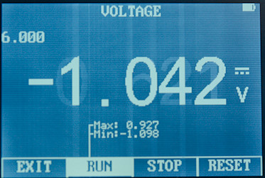
The above picture shows all the segments on the display. There is two 5 digit displays and a bargraph. The number at the end of the bargraph shows the range.
![DSC_7608]()
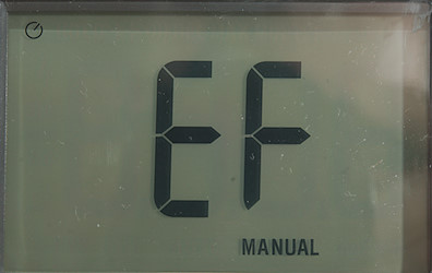
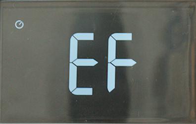
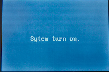
Standard turnon display shows the meters model number and the firmware version.
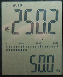
![DSC_7592]()
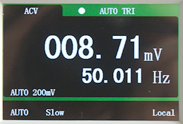
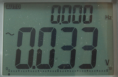
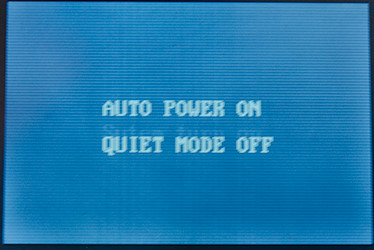
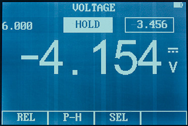
Normal display with the measurement, unit, bargraph and temperature (The secondary display will show meter temperature when nothing else is selected).
![DSC_7593]()
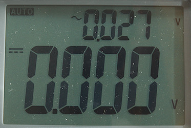
A secondary measurement is selected.
![DSC_7594]()
NCV (Non contact voltage) or Vsense in Keysight terminology, the range button will select between “Hi” or “Lo”.
![DSC_7595]()
Square wave out, both frequency and duty cycle can be adjusted.
![DSC_7617]()
One item in configuration menu, all items is identified with a name written in the display.
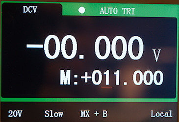
Dual and single display functions (After / is small display):
mV+VAC: VAC/temp, VAC/Hz, dBm/VAC, dBV/VAC,
mV+VDC: VDC/temp, VDC/Hz, dBm/VDC, dBV/VDC
mV+VDC-AC mode: VAC/temp, VAC/freq, dBm/VAC, dBV/VAC, VAC/VDC
mV+VDC-AC+DC mode: VAC+VDC/temp, VAC+VDC/freq, dBm/VAC+VDC, dBV/VAC+VDC, VAC+VDC/VAC, VAC+VDC/VDC
uAmA DC: A/temp, A/freq, %4-20/A, %0-20/A
uAmA AC: A/temp, A/freq, A/ADC
uAmA AC+DC: A/temp, A/freq, A/AAC, A/ADC
A: A/temp, A/freq
A AC: A/temp, A/freq, A/ADC
A AC+DC: A/temp, A/freq, A/AAC, A/ADC
Frequency: freq/main, pulse-time/main, duty-cycle/main (Main will be V/A AC/DC/AC+DC depending on rotary switch and selection)
Freq out: duty-cycle/freq
Functions
![DSC_7600]()
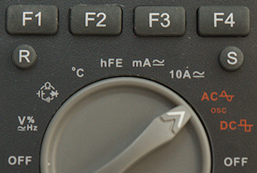
Buttons:
- MaxMin: Select max/min function, pressing again will select between max/min/avg/actual, hold down to exit. If held down initially peak is selected, press to select between max/min.
- Null: Store current value and show new values relative to this, pressing NULL while active will show the saved reference. Double press to cancel, hold down to activate NCV (Range switch is ignored).
- Range:
- Select manual range, hold down to exit
- In ohm this will also select conductivity (nS) mode.
- In continuity it is possible to change range and thereby threshold
- In MHz frequency counter mode it will enable MHz mode that has higher upper frequency.
- In temperature mode it will switch actual temperature compensation on/off.
- Hz: Show frequency, duty-cycle or pulse-time on the large digit, the old value will often move to secondary display
![light]() : Turn backlight on, hold down to change dual display mode. When showing duty-cycle or pulse time it will change polarity.
: Turn backlight on, hold down to change dual display mode. When showing duty-cycle or pulse time it will change polarity.
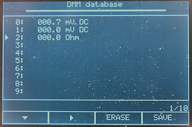
- Shift (Orange): Select the ranges marked with orange on the rotary switch. Hold down to review saved values. In frequency output it will change between duty-cycle and time mode.
- Hold: Hold and save the value, press again to start auto-hold for next stable value. Hold down to save a value or start logging (This depends on configuration).
Buttons in configuration:
- Null: Digit increase
- Dual: Digit decrease
- Hz: Save change
- ESC: Abandon change or exit configuration.
- Hold: Next/previous menu item or digit left/right.
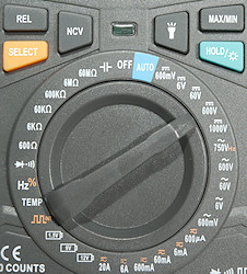
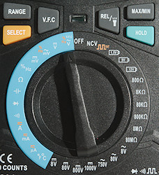
Rotary switch:
- Off: Meter is turned off.
- VAC: Measure VAC, use SHIFT to enable low pass filter and DUAL to show dB
- mVAC: Measure mVAC, use SHIFT to enable low pass filter and DUAL to show dB
- VDC: Measure VDC, VAC voltage and VAC+VDC voltage, use SHIFT to select.
- mVDC: Measure mVDC, mVAC voltage and mVAC+mVDC voltage, use SHIFT to select.
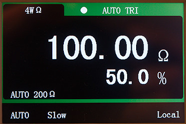
![ohm]() : Resistance and continuity, use RANGE to select nS
: Resistance and continuity, use RANGE to select nS
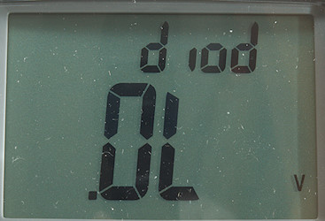
![diode]() : Diode and frequency, use RANGE to enable high frequencies.
: Diode and frequency, use RANGE to enable high frequencies.
![c]() : Capacitance and temperature.
: Capacitance and temperature.
- uA mA: Low current, this meter will automatic switch from uA to mA, use SHIFT to select AC/AC+DC
- A: High current, use SHIFT to select AC/AC+DC
![out]() : Frequency out mode.
: Frequency out mode.
dB reference impedance can be adjusted from 1ohm to 9999ohm
Frequencies: 0.5, 1, 2, 5, 6, 10, 15, 20, 25, 30, 40, 50, 60, 75, 80, 100, 120, 150, 200, 240, 300, 400480, 600, 800, 1200, 1600, 2400, 4800
Duty cycle is changed with less than 1% steps, but not in round values.
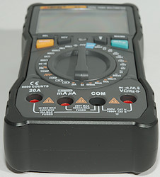
Input![DSC_7601]()
- A: High current, maximum current is 10A.
- mAuA: The lower current ranges and frequency output
- Rmt: Remove control with special probe, can be used to trigger HOLD and save or any other of the 7 buttons.
- COM: The common terminal for all ranges.
- xxx: All other ranges.
Measurements
- Volt and frequency
- Frequency input will trigger from -1.1V to 2.4V offset with 0.1Vrms input.
- At 0.1Vrms frequency input range is from 0.4Hz to 800kHz
- At 1Vrms frequency input range is from 0.4Hz to 1.8MHz
- At 1Vrms frequency input range with MHz setting can reach 36MHz but shows to high above that.
- According to the manual the frequency input is for signals below 1.8Vp, use voltage input for larger signals.
- VDC input has a trigger point around 0.2V for frequency input.
- VAC input ignores any DC offset for frequency input.
- At 1Vrms input on VAC range, frequency range is from 0.4Hz to 650kHz
- Duty cycle works from 10% to 90% at 10kHz with 1Vpp, precision is within 3.0 (Higher voltage do not help)
- 1 VAC is 5% up at 70kHz (RMS will not work at the frequency).
- 1 VAC with LPF (VFD) is 5% down at 500Hz.
- Auto range works when doing min/max, but makes it very slow.
- Auto range works in relative mode.
- Max/min needs about 1900ms to capture a voltage and 400ms if manual range is selected.
- Peak needs about 0.25ms to capture a voltage, it uses manual range.
- Input impedance is 10Mohm on DC
- Both AC inputs has a capacitor
- Auto ranging is rather slow on this meter.
- mV DC has 10Mohm or high input impedance depending on configuration to about 2V, then it drops to a few kOhm.
- Rated overload protection is 1000Vrms, on mV it must be limited to 0.3A
- Current
- Overload protection in uA and mA: 0.44A/1000V 10×38mm fuse
- The meter will auto range between uA and mA
- Overload protection in A: 11A/1000V 10×38mm fuse
- DCuA & mA can show percent of 0-20mA or 4-20mA range.
- There is an audible warning and display shows “Lead” when using non current ranges without a probe (This warning is time limited).
- There is an audible warning and display shows “uAErr” when using non current ranges with a probe in mAuA input (Buzzer is time limited).
- There is an audible warning and display shows “A-Err” when using non current ranges with a probe in mAuA input (Buzzer is time limited).
- Ohm, continuity, diode and capacitance
- Ohm needs about 3.2s to measure 100ohm
- Ohm is 1.1V open and 0.99mA shorted
- Conductivity (nS) is 1.1V open and 0.2uA shorted
- In conductivity it is best to keep some distance to the meter, especially when measuring Gigaohm.
- Continuity is very fast (Below 10ms).
- Continuity beeps when resistance is below 16ohm (3ohm in 60ohm range and 80ohm in 6kohm range).
- Continuity is 2.2V open and 0.99mA shorted
- Continuity allows range shift, this will change the threshold between 5ohm and 100kOhm.
- Diode range uses 3.3V, max. display is 3.1V at 0.1mA, max. current is 1.5mA shorted
- 10uF takes about 6.5 seconds to measure.
- 11000uF takes about 50 seconds to measure.
- Rated overload protection is 1000Vrms limited to 0.3A
- Miscellaneous
- Current consumption of meter is 2.5mA in DC, 5.3mA in AC and 11.3mA when high frequency counter is activated (42mA with backlight in AC)
- Meter works down to 3.9V where it turns off, battery symbol starts flashing at 4.3V.
- The meter reading is stable until it turns off.
- Backlight fades with voltage, but is still usable when meter turns off
- The meter usual need a couple of updates before the reading is fully correct.
- The meter is very slow (Up to a few seconds) to change range.
- Viewing angle is good
- Display updates around 5 times/sec.
- In high speed mode the display will update around 50 times/sec and the resolution is reduced to 6000 count.
- Bargraph updates 40 times/sec
- Backlight and automatic power can be configured.
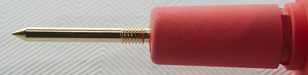
- Standard probes fits perfectly into sockets on meter.
- To update software in the meter you must download and install a software updater program for this meter.
- Weight is 703g without accessories, but with batteries.
- Size is 220 × 101 × 58mm.
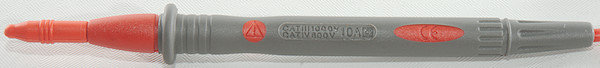
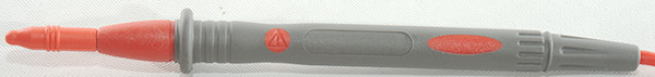
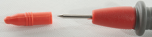
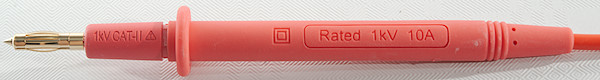
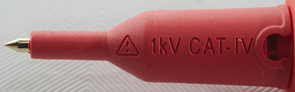
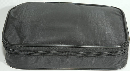
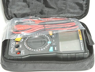
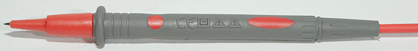
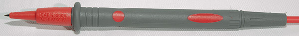
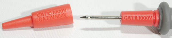
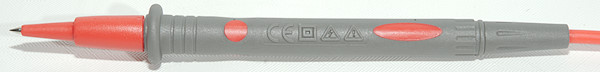
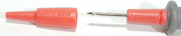
- Probes
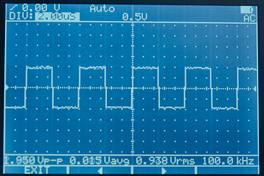
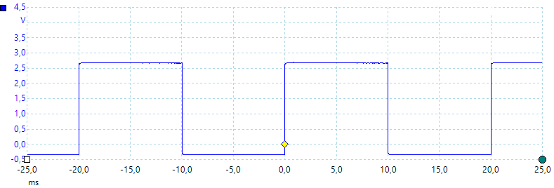
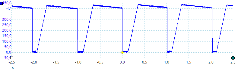
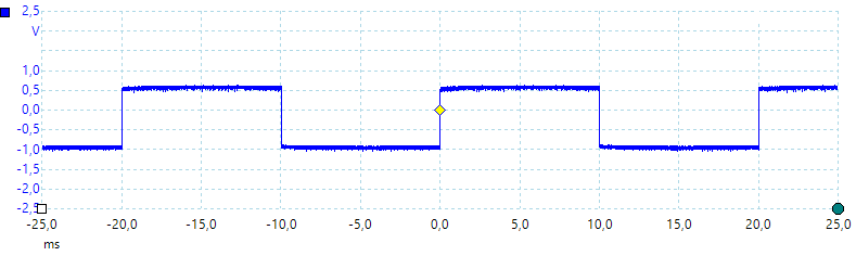
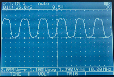
![Freq600Hz50pct]()
Default frequency output of 600Hz at 50% duty cycle. The signal level is fine for 3.3V logic, but too low for 5V logic, especially
CMOS.
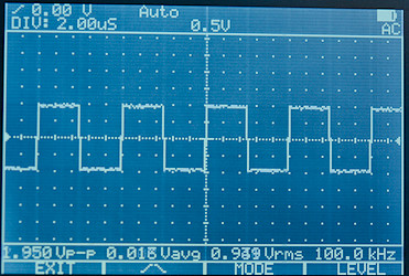
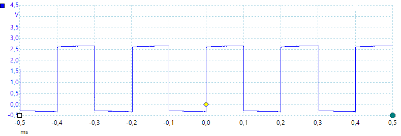
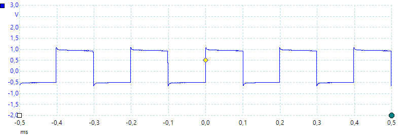
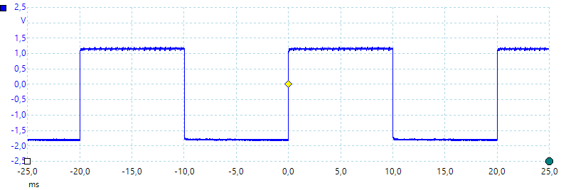
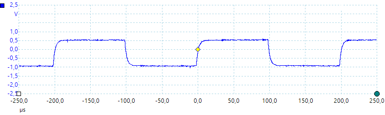
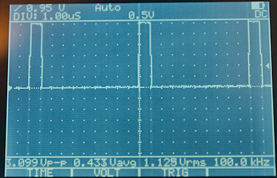
![Freq4800Hz039pct]()
Fastest output at 4800Hz and 0.39% duty cycle.
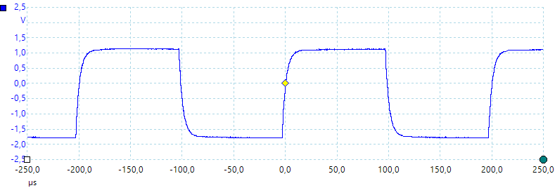
![Freq4800Hz039pct1]()
A closer look at the pulse.
![Freq05Hz50pct]()
Lowest frequency is 0.5Hz.
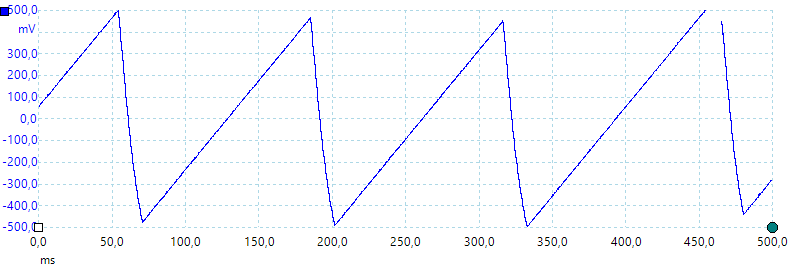
![Freq600Hz50pct460ohm]()
Output loaded with 460ohm, this about halves the output level, i.e. output impedance is around 460ohm.
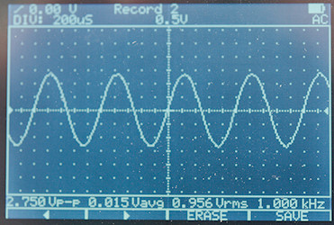
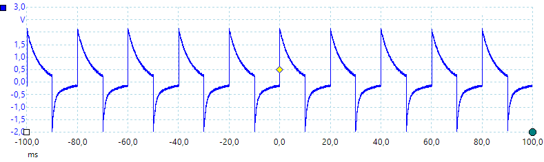
![1uF]()
A look at the capacitance measurement waveform.
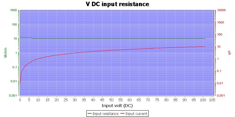
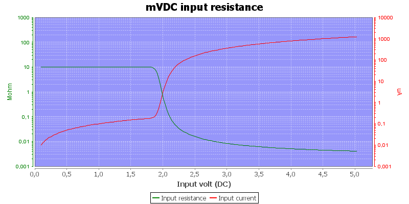
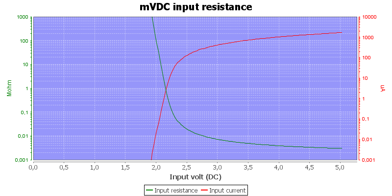
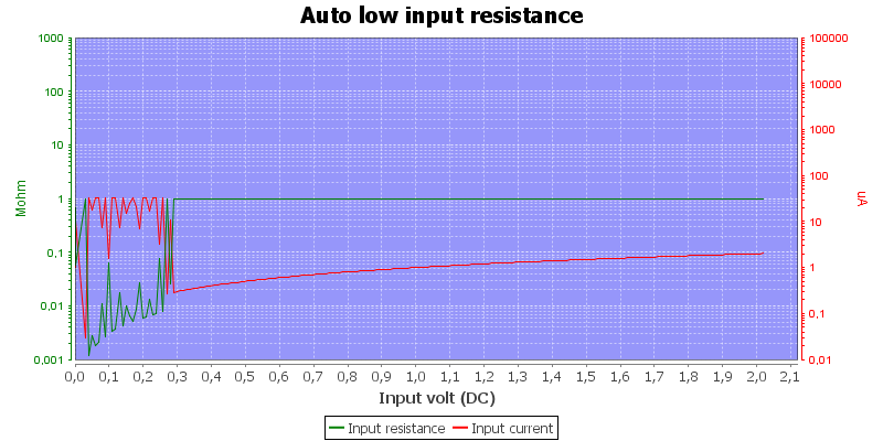
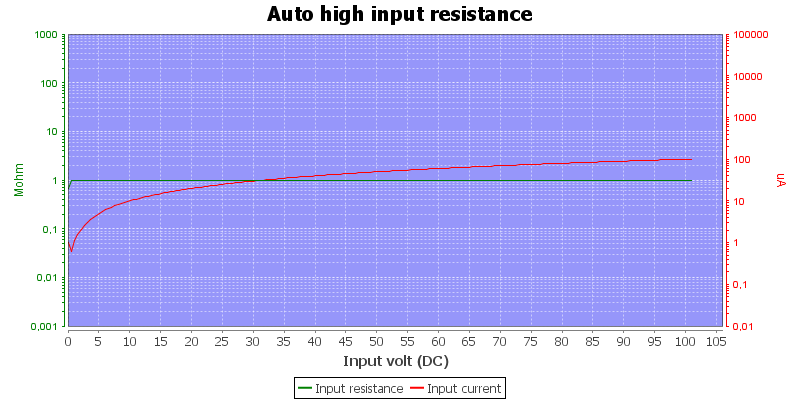
![DMMInputVoltageSweepmVDCHighZ]()
DC input impedance in high-Z mode, the 10Mohm mode is similar, except maximum impedance is 10Mohm.
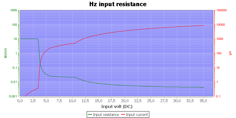
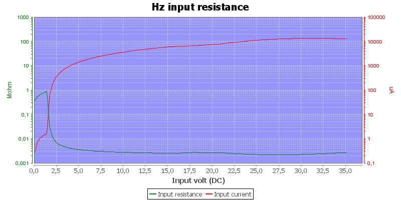
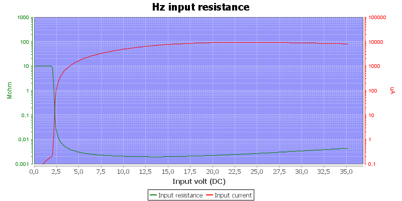
![DMMInputVoltageSweepHz]()
Frequency input resistance, this is designed for fairly low signal level and is not the usual logic level input.
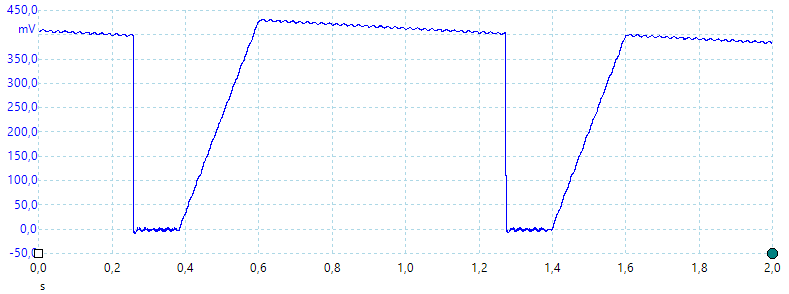
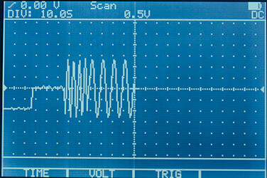
![uAmAAutoRangeSpeed]()
How fast is auto ranging between uA and mA, here I start with zero current and turned 100mA on from a 1V supply.
It takes 3 seconds to auto range, this means that a micro processor that has a pulsed current consumption most likely would reset, i.e. manual ranging must be used.
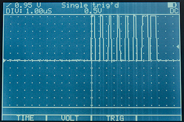
![uAmAAutoRangeSpeed2]()
Next I start with zero current and turned 400mA on from a 9V supply.
With higher voltage the protection kicks in and limits the voltage and current in the sense resistor, the auto ranging is also slightly faster.
![DMMschema]()
Runtime is based on AC range, i.e. 5.3mA power consumption, Keysight uses DC in their specifications.
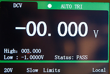
Configuration
There is many configuration options on this meter:
- AutoHold: Number of counts the reading must go outside to rearm autohold and restart smooth.
- Time: Enable/disable smooth mode and smooth mode time.
- Auto power off time: How many minutes before meter powers off, auto power off can also be disabled.
- Backlight time: How many seconds before backlight turns off, auto off can also be disabled.
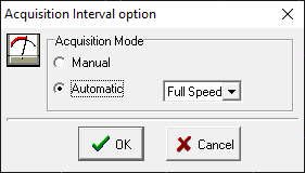
- Logging type: Select between manual, auto or interval logging.
- Time: Sample interval when logging.
- dBm reference: Can be set from 1ohm to 9999ohm
- Thermocouple type: Either K or J
- Temperature unit: Either Celsius or Fahrenheit.
- Beep frequency: Select between some frequencies or off.
- Startup sound: Select between beep, melody or off.
- Alert: Define if warning uses beeper and/or led or nothing
- Battery type: Select between primary (Alkaline) or secondary (NiMH) for more precise battery meter.
- Factory default: Reset to factory default.
- Remote button: Define function for remote button, can be mapped to any of the 7 buttons.
- Resolution: Select between 60000 or 6000 count display
- Update speed: 5 or 40 updated each second, the fast speed means 6000 count display.
- Input impedance: Select 10Mohm or high for mV ranges.
- LPF: Select default with or without LPF, this also supports LPF on DC.
Software on PC (Handheld Meter Logger Software)
- Software is free to download and listed as free software on Keysight.
- In addition to the software there is also installed License manager, License service and Agilent Host Processor Platform.
- Report generator in software is fairly limited, it only accepts 200 samples.
- It is only possible to generate a word or PDF report if Word or a PDF viewer is installed.
- The software ignores the secondary display and value.
- On my laptop the window is covering the laptops battery indicator.
![DSC_7610]()
The
USB to IR cable.
![DSC_7590]()
The IR adapter connected to the meter.
![1s]()
It took some time to install the software.
![2]()
And during the install I got this message, I wonder why it could be show this at the start of the install.
![3]()
First question when starting the application
![4s]()
During startup the software shows this logo, notice the date. It will check for new versions each time, with a 4 year old software this is a bit much.
![18s]()
Lets check the licensing, it do not say anything about free here and the “Lear More” shows a Keysight login, not very helpful.
![16s]()
The program has a couple of settings, the voice out function will read the displayed value at regular time intervals, not when the value change.
![6s]()
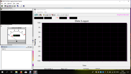
Starting the program shows a nearly empty screen, sometimes it will auto connect to a meter.
![7s]()
A fairly generic meter box that is used to for connecting to the meter.
![5s]()
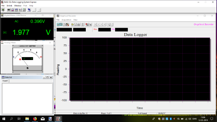
When connected this is the main screen.
![8s]()
It is possible to change some settings on the meter from here. Software will update if ranges are changed on the meter.
![10s]()
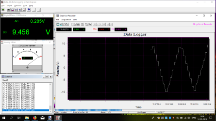
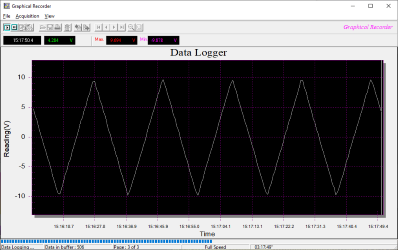
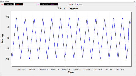
A bit of logging, the first part was with the meter in auto range, the last part of the curve used manual range and I got a much smoother curve.
The scale is not very nice, I would have preferred a scale with 15, 10, 5, 0, -5, -10, -15.
![12s]()
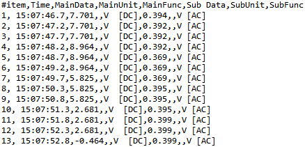
Data can be viewed as a table on multiple pages.
![13s]()
Another window will show the actual value on the meter, but the secondary display is ignored.
![14s]()
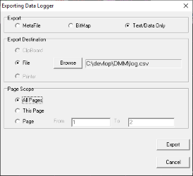
Report generator, with 3 different reports, but they are basically the same.
![15s]()
Selecting data to include in report, maximum is 200 data points.
![17s]()
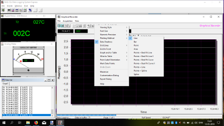
In the chart interface it is possible to enable two cursors to measure with.
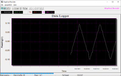
![charts]()
A chart saved from the chart window, again the scale is bad.
![docs]()
The report format, either chart or table can be missing, depending on format selected. The table format may be useful for single log points, but not when logging continuous, I do not need fill time, function and unit for each line. I would have preferred a much more compact format.
![xmls]()
When logging a
XML file is automatically saved, the format is not exactly compact.
![log]()
The
CSV file is more to the point and except for the top it is a standard
CSV file in US format.
Software on Android (Mobile Meter)
- This software can be downloaded from Google Play store.
- With a U1117A/U1177A Bluetooth adapter it is possible to connect to a phone.
- Keysight do not support their mobile software “Keysight Mobile Meter” anymore
- App has copyright 2015 and is version 2.2.0
![DSC_7612]()
![DSC_7613]()
![DSC_7614]()
The meter has no build in Bluetooth, but requires an external adapter.
![DSC_7609]()
It is not the most discrete solution when mounted on the meter.
![8s]()
![9s]()
When starting I am warned that the software is unsupported, I could not download the new app from Google. I had to connect the adapter using Andriod Bluetooth, then I could connect here.
![7s]()
The readout do not use much screen estate.
![1s]()
Turning the phone over improved the display size.
![6s]()
I have to press the green button to start scanning, the first value is fetched when connecting, but not updated.
![2s]()
The
SHIFT modes on the meter can be controlled from the app and like the PC application the secondary display is ignored.
![4s]()
It is possible to share the single value.
![5s]()
The phone support reading the value at fixed intervals.
![3s]()
It is possible to connect up to 3 meters.
![10s]()
Confirmation when quitting the application, just leaving the application will not stop it and if reading is enabled it will continue.
Software on Android (Meter Logger)
- This software can be downloaded from keysight.com and must be manually installed on the phone (I could not find it on Google play).
- With a U1117A/U1177A Bluetooth adapter it is possible to connect to a phone.
- App has copyright 2017 and is version 3.1
- With the U1117A I got about 5 meter indoor range through a thick wall, no other Bluetooth meter has done that.
- It recovered easy from breaks in communication.
![DSC_7612]()
![DSC_7613]()
![DSC_7614]()
The meter has no build in Bluetooth, but requires an external adapter.
![DSC_7609]()
It is not the most discrete solution when mounted on the meter.
![1s]()
![7s]()
![10s]()
With this app there is both a value and a curve and either of them can fill the screen.
![15s]()
The app supports up to 3 meters.
![2s]()
![8s]()
![9s]()
If I flip the phone it works the same way and the layout is adjusted.
![3s]()
![4s]()
![5s]()
![6s]()
There is a lot of configuration. The voice output is not very useful when the phone uses a “,” as decimal comma, because the app use a “.” and it is not spoken.
![11s]()
![12s]()
In addition to the chart it is also possible to get a table or min/max/avg values from the recorded data.
![13s]()
There is a local database to keep track of recorded data.
![14s]()
And it can be shared, tried with email and it worked fine.
![log]()
The data is a US
CSV format, but I wonder why I need information about meter and Bluetooth adapter on each line.
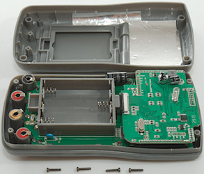
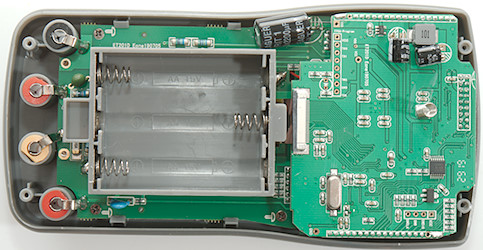
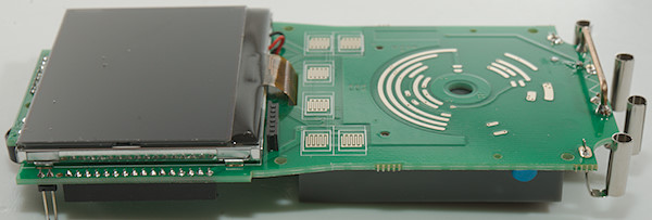
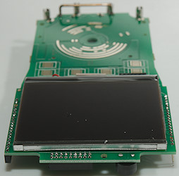
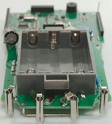
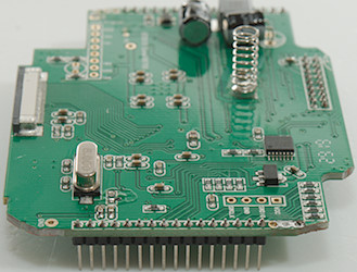
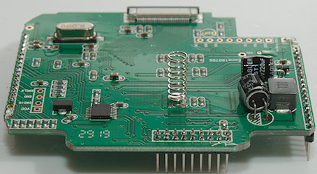
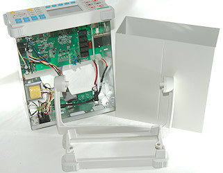
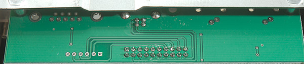
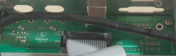
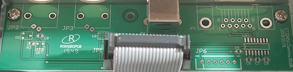
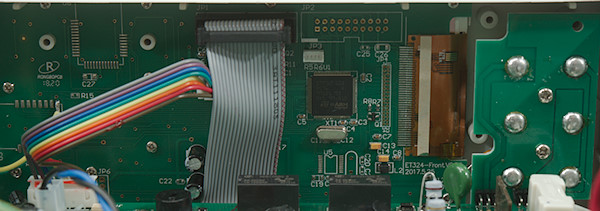
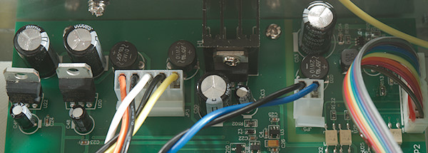
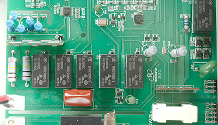
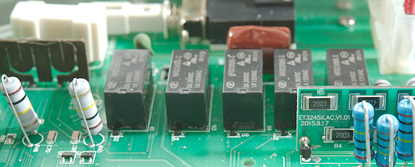
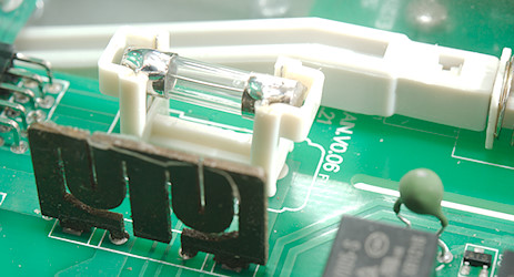
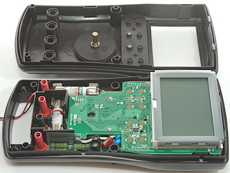
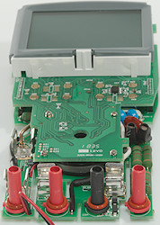
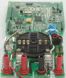
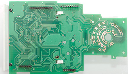
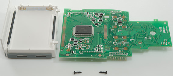
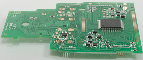
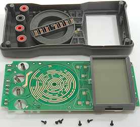
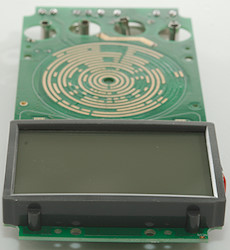
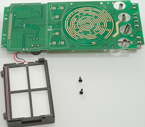
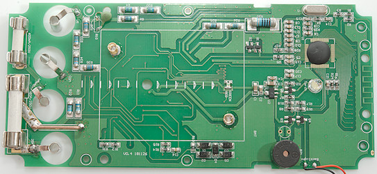
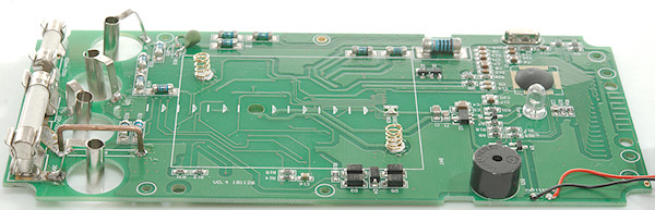
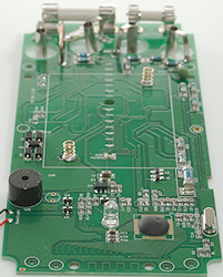
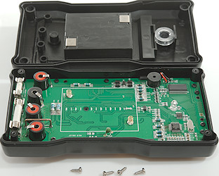
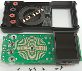
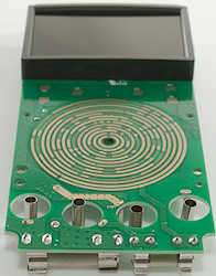
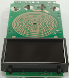
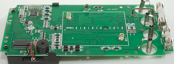
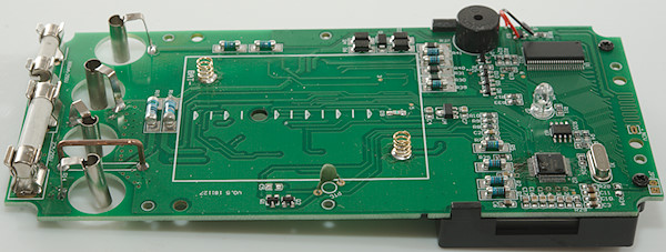
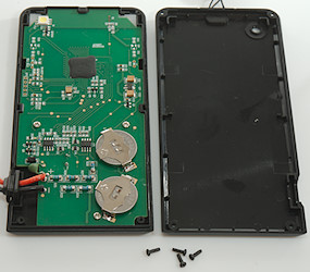
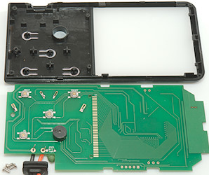
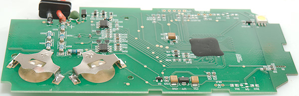
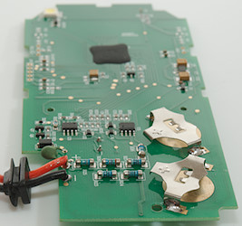
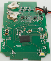
Tear down![DSC_7629]()
I had to remove 6 screws to open the meter.
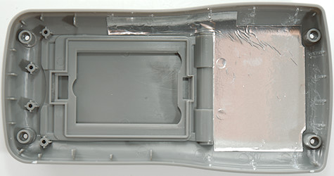
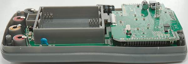
![DSC_7630]()
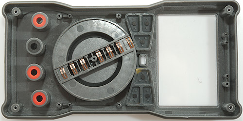
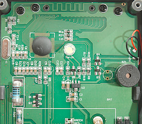
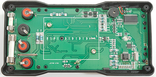
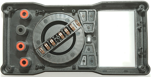
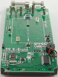
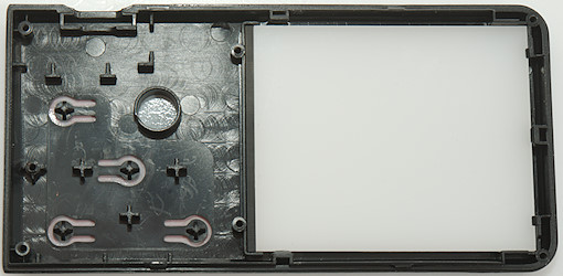
The buzzer is in the back cover of the meter, connected with thin wires and a small connector.
![DSC_7632]()
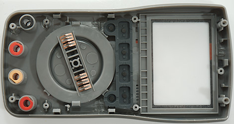
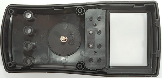
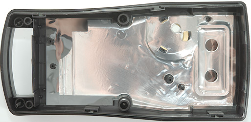
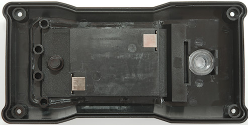
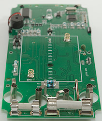
There is a lot of shields moulded into the back cover.
![DSC_7633]()
![DSC_7634]()
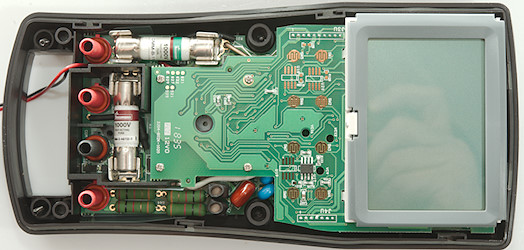
There is some shielding beside the voltage input resistor, that already is in a metal box.
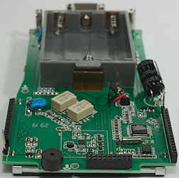
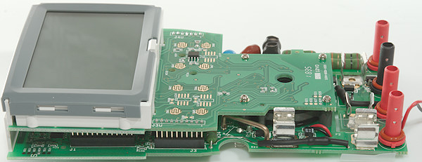
![A001s]()
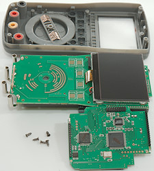
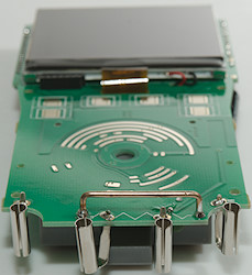
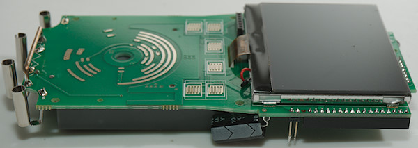
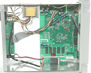
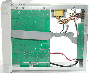
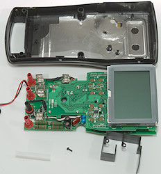
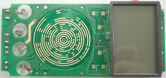
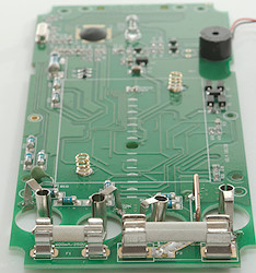
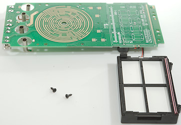
The circuit board was a bit tricky to get out, I had to unhook four connections.
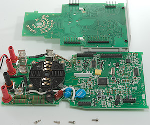
![DSC_7635]()
Then remove 5 screws and four nuts.
![DSC_7636]()
![DSC_7638]()
A view of all the plastic shields moulded into the enclosure.
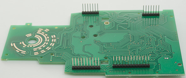
![DSC_7639]()
![DSC_7640]()
![DSC_7641]()
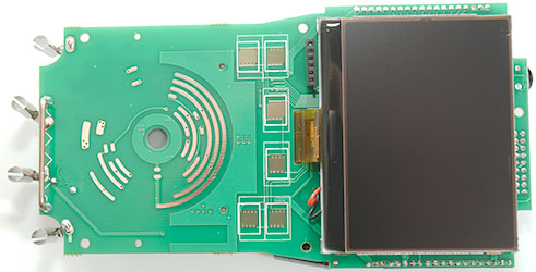
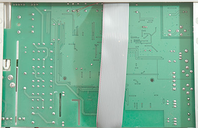
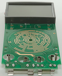
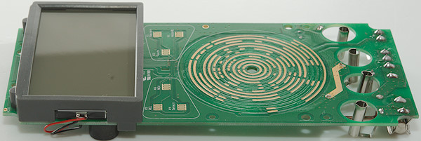
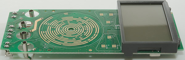
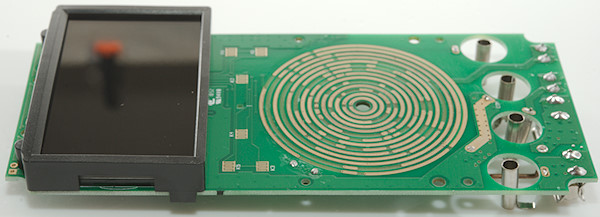
The
LCD display was only mounted with one screw.
![DSC_7642]()
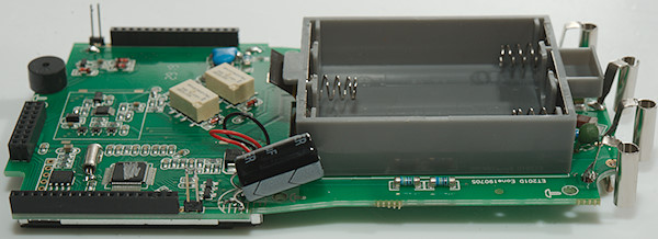
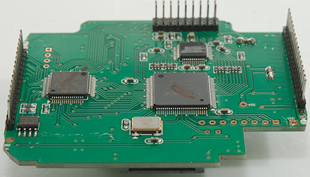
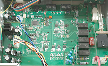
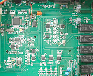
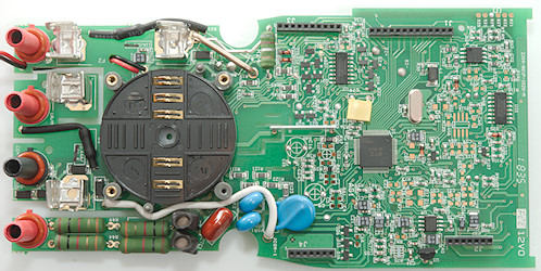
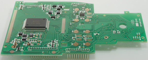
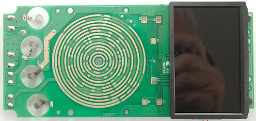
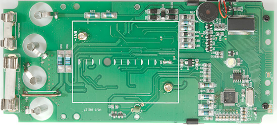
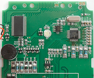
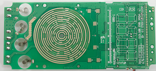
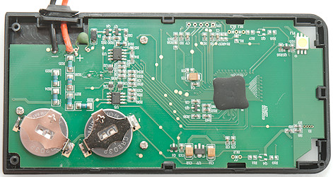
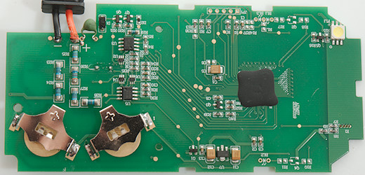
On this side is the main processor (U27: D78F0485: Renesas 78K0/LF3, 8bit, 60kB
ROM, 2KB
RAM,
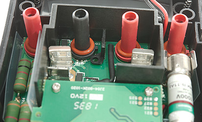
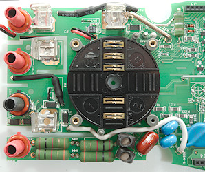
LCD driver), next to two shift registers outputs (U18 & U19: LV595A). At the input terminals are some diodes (D1..D4), half the uAmA shunt protection and two resistors (R137 & R138: 2×2.5Mohm) protection resistor for the terminal sense. The circuit is the uAmA current sense circuit.
The range switch has a large distance for the two outer rings (on both sides), they are used to switch the input terminal and can have high voltage.
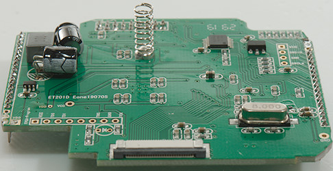
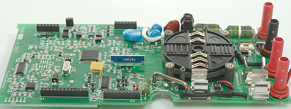
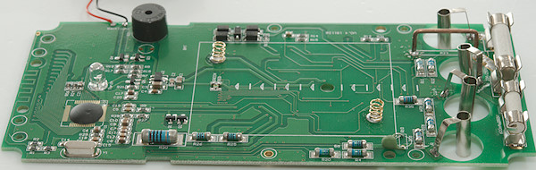
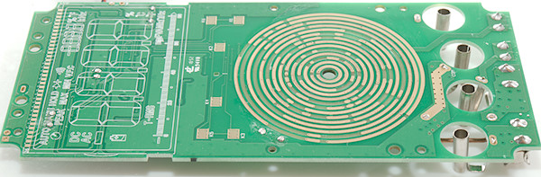
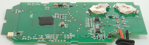
![DSC_7654]()
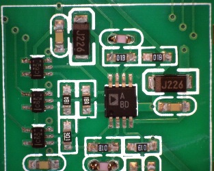
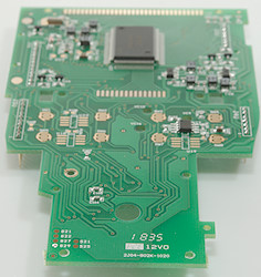
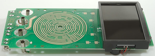
The large resistor (R106: 0.499ohm), this is lower than normal. There is a OpAmp (U24:
AEJY: MAX9912 Dual RR OpAmp), the other chip (U15: S48) may also be an OpAmp. The uA shunt and range switching transistor is on the other side.
![DSC_7643]()
![DSC_7644]()
![DSC_7646]()
![DSC_7645]()
![DSC_7647]()
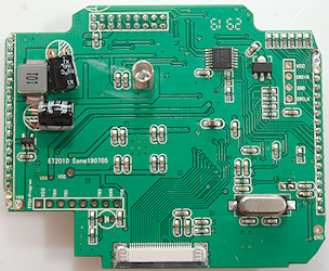
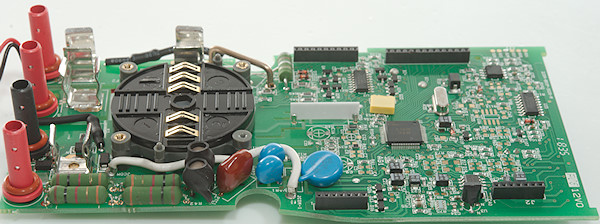
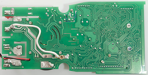
At the common terminal is four mode diodes (D5..D8) for uAmA protection and a
PTC (RT5) protection for the remote switch.
The uAmA circuit is opposite the circuit on the other side, but I am a bit puzzled about it. The two transistors (Q1 & Q2: Marked X07V / 1F) can bypass this circuit and only leave the resistor on the other side active, next there is two resistors (R15: 499ohm & R16 56ohm) where the R15 can be bypassed with another set of transistors (Q3 & Q9: Marked X07V / 1F), but I did never see a 500ohm impedance when measuring current (I checked DC, AC and AC+DC).
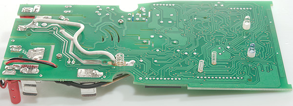
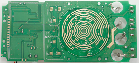
The voltage input has two paths with
MOVs (RT1 & RT2) and resistors (R1 & R2: Measures about 270ohm), then a capacitor for AC (C4: 100nF 630V) and a shielded input resistors on a ceramic substrate (R3) going directly to the main multimeter IC (U5: HY3131). There is no
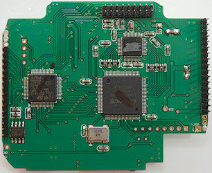
MOV’s, but instead spark gabs (VR1 & VR2) on the other side of the circuit board.
I do not see any transistor pairs, instead the protection for ohms, frequency, temperature, etc. is width diodes (D9, D10, D11, D12, D13, D22, ZD3, ZD4) in these ranges (The two path from input arrives at BD2 and BD4).
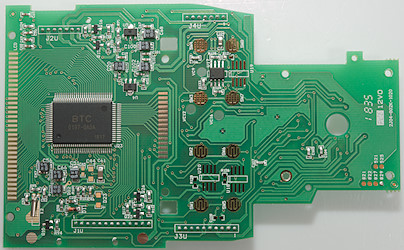
The chip (U20: S/6B) is probably the frequency output amplifier, it has 600ohm from pin 8 to the uAmA output in frequency output mode. This resistance is somewhere in the uAmA circuit.
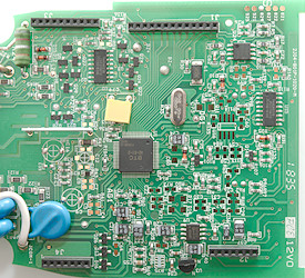
In addition to the main multimeter IC there is a
RMS converter (U13: AD8436A) a couple of
MUX’es. The meter has memory for 10100 readings (Probably: U28 marked ATNLH4482FC).
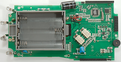
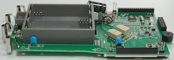
To get enough sound from the buzzer there is an inductor (L1) next to the buzzer connector. The inductor is glued in place.
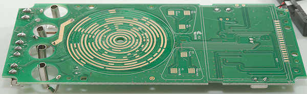
![DSC_7653]()
![DSC_7655]()
More details.
![DSC_7648]()
![DSC_7649]()
![DSC_7651]()
![DSC_7650]() Conclusion
Conclusion
This meter has good input protection.
There is basically everything in ranges and functions, if you can find it, some ranges/functions needs the use of
SHIFT,
RANGE and
DUAL and there is no obvious hints on the meter about it. Usage of the
DUAL function is also a bit slow with up to 5 long pressed to get a specific readout (2xSHIFT + 5xDUAL to get AC+DC with DC in secondary display). The meter measures fairly fast, but any range or mode changes is very slow.
The complete lack of support for the secondary display in all the software limits some of the functionality.
If you want a meter that has a very wide selection of ranges and functions and is
patient this meter is a good candidate.
Notes
I have used this meter for logging with my own software, it is fine for that, but replacing batteries are a bit of a hassle.
How do I review a DMMMore DMM reviewsMultimeter design, this explains a lot more about DMM’s than my tear-downs


 : Turn flashlight on or off
 : Hold down to turn power on/off, press to change between auto/VDC/VAC/Continuity/diode/capacity


 : Arrows and


 : Select Capacity, Diode, Continuity, ohm (Not the usually sequence).


 : Press to freeze/unfreeze current reading, hold down to turn on background light,
  : Press to use relative mode (
 : Resistance, continuity and diode
 : Capacitance


 : Shows values relative to current value.
  : Resistance and continuity, the nS makes it possible to measure very huge resistance
  : Capacitance and diode range.


 : Turns the flashlight on.
 : 12V Battery test
 : 9V Battery test
 : 1.5V Battery test
 : Frequency output from 50Hz to 5000Hz, use
  : Continuity and diode mode, there is no selection, it is a single mode that do both and for a combined mode it works fairly well.
 : Capacity
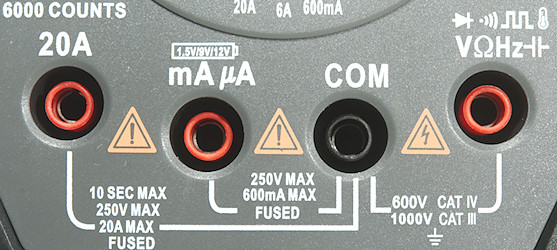


 : Frequency output from 50Hz to 5000Hz, use
  : 12V battery test
 : 9V battery test
 : 1.5V battery test.
 : Continuity
 : Diode
 : Capacitance
 : Resistance
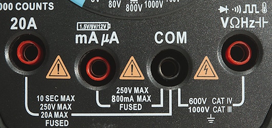
 : A press on this button will turn the meter on or off. Both on and off only requires a short press.
 : A short press will turn on the flashlight.


 : Turn backlight on, hold down to change dual display mode. When showing duty-cycle or pulse time it will change polarity.
 : Resistance and continuity, use
  : Diode and frequency, use
  : Capacitance and temperature.
 : Frequency out mode.


 : ohm, diode, continuity and capacity, use F3/SEL to select.
 : Oscilloscope mode with AC input
 : Oscilloscope mode with DC input
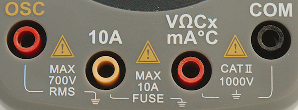
 z
z